I have been given a Nintendo Switch (HAC-001) to repair - however I am at a loose end and could really do with the schematic/boardview .brd file for this please.
It’s for the HAC-CPU-20
Originally customer sent it in with BSOD…but
Customer informed that it was dropped on the stairs - but during the dissemble process I am fairly sure it must have bounced down at least a couple of stairs (at the least).
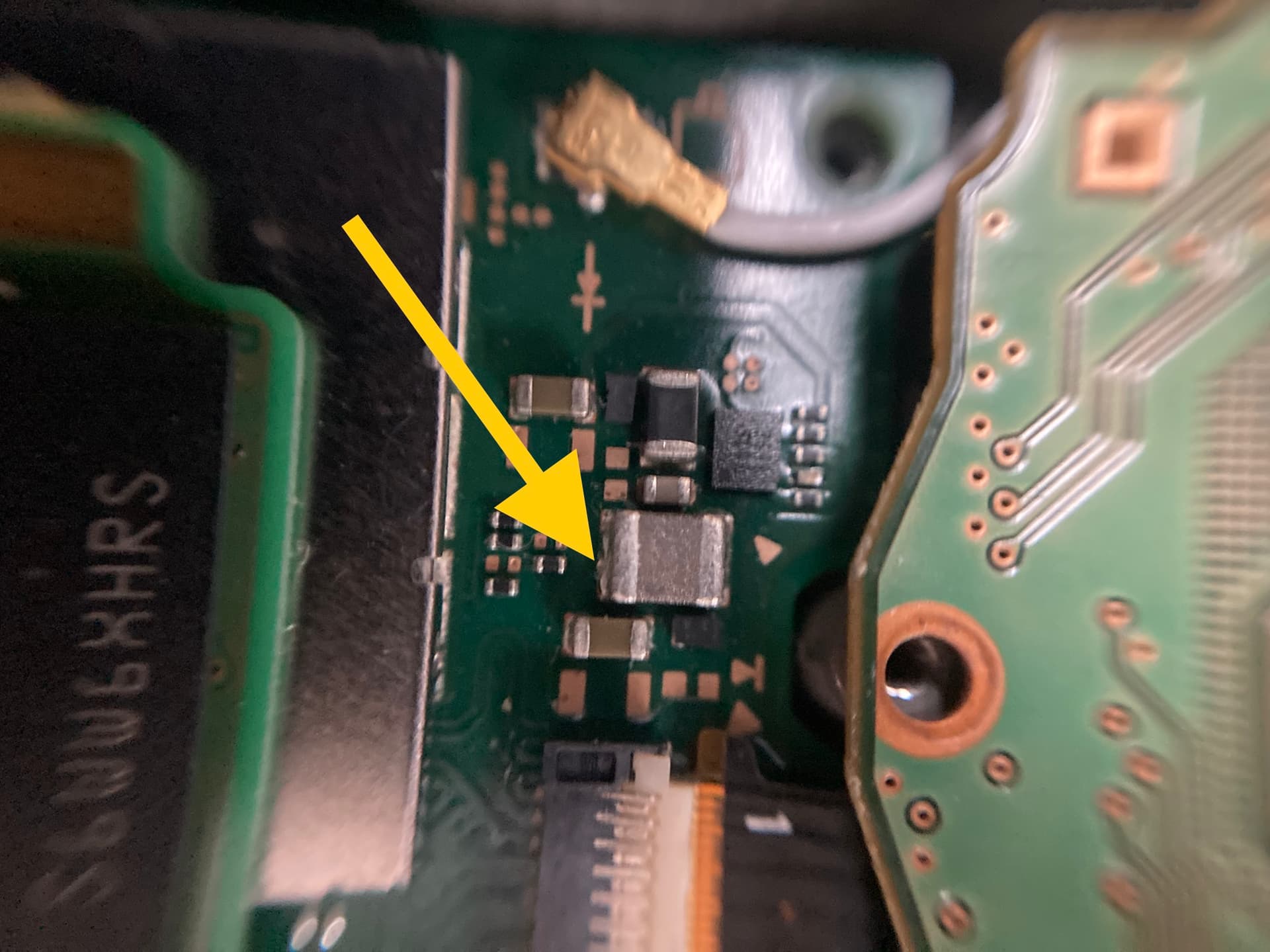
The LCD connector requires replacement and (what I believe to possibly be a Filter/fuse) is shorting to ground, so I need to track down exactly what it is, what size it is and pick up a replacement pronto.
Anyone who can kindly help me would be extremely grateful.
Paul
I have done a little bit of digging and in fact I am not entirely sure it is a fuse, and is actually a multilayer capacitor that is shorted. It is sitting next door to the LCD zif connector.
That’s the only fault I am spotting at present, apart from the zif connector that will need swapping out… looks like one of the pins to the zif connector has dislodged and caused the short circuit.
Can’t see anything else at present
Hi Insomniac
Thank you for that information.
I am normally pretty good at identifying the smaller smd components but how did you identify that as an inductor?
Paul
Mostly by shape an colour, black tends to be a resistor, yellow-ish a capacitor and grey an inductor. In this case I also just know that it is, as it it part of the voltage supply circuit for the LCD. On my board here is has about 2 Ohms to ground so will read as a short in continuity mode.
So until my zif connector arrives… I can definitely see that one if the pins had dislodged and caused a short (browned minor burn mark) on the zif connection.
I have managed to pop the pin back in place but I am no longer getting the BSOD and instead just got a blank screen with no power.
Any thoughts… better still do you have a schematic / boardview file for this board that I could follow please?
Paul
When you plug it into a 12v PD charger, what voltage and amps is being drawn? I had a similar issue that was the LCD connector shorted. Sometimes the connector will get warm too. Replacing the connector fixed the issue. Your best bet is replacing the connector to see if it fixes the issue.
Hi…
I have a PD charger rated 20W that I can use.
Which points do I need to check so as to provide you with the voltage and amps required.
I will definitely be swapping out the connector, and the screen has been sent to me in a scratched up state, and they require the screen swapped out so a new screen and zif connector will hopefully sort this issue.
My question is… the BSOD??? could this be the cause of the BSOD or is there something more serious that I am missing.
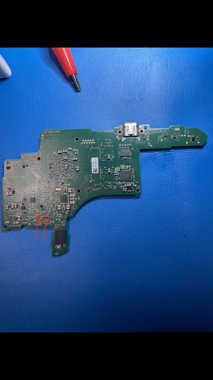
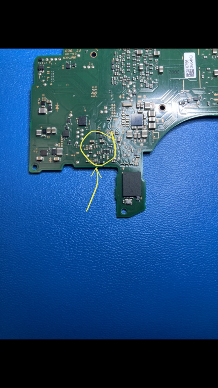
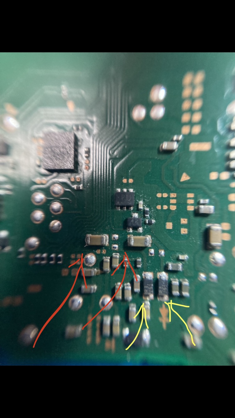
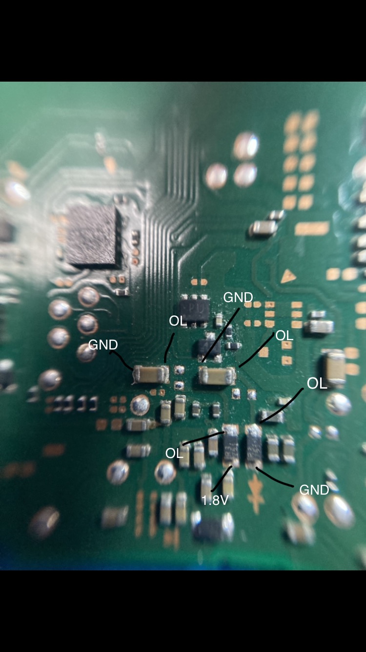
I ran a diode check on a some of the components on SIde A (opposite side of zif connector - but posiitioned on the reverse to where the connector is —
I have however come across a couple of Caps (might not even be related to the LCD but with that faulty connector still in place)which have caused 2 to read GND one side and OL on the other. (Pics to follow)
Pictures are as follows:
*Note. I have taken a few photos zoomed out as well as midrange zoom and finally a close up so as to identify the components location.
@iBringsTheRuckus - I do have a USB tester that I can connect in-line but that will be tomorrow now as it’s gone midnight here in the uk
Kind regards
Paul
I dont think any of those caps are showing problems. Start with the connector for now. If you still have a blue screen after than then we can start investigating. My first port of call would be to boot it while applying firm pressure to CPU and RAM (one at a time, not all together) to see if it can boot like that. If so, you have your culprit and it will need to be either reflowed or, ideally, re-balled.
This connector will not lift off for me.
I’ve tried without flux and also with flux but it just won’t budge. I cranked my reflow up to 350 degs at just over half power.
Worked perfectly fine on an old test board of mine - incase it needed recalibrating.
Obviously I don’t want to fry the board or damage the traces
Any ideas / suggestions??
Paul
On mine I heat from under the board, at 450 or 480, at something like 70% air flow to get them off. I lower heat a bit when putting them on as using leaded solder.
@Insomniac
Thank you for your help… I ended up getting the big guns out….ended up using a tiny bit of low melt solder because even trying your method would not budge the b.
The pads are all cleaned up and ready for some leaded solder hopefully tomorrow, but it’s school holidays so have to make sure I set some time aside to spend with my son as well
Bluescreen after falling is often caused by broken solder joints under the CPU or RAM, so you probably have to reflow These.
You can try First as @Insomniac wrote to apply some pressure in them and See if the console will Boot normally than.
Otherwise Check if the battery fuel gauge looks fine and is Not riped of or cracked.
@Insomniac@rip-it-up@zyrex
I have never done a reball before…….
Do you need special equipment to do this???
I have watched a few YouTube videos and some have bought a rather expensive piece of equipment to help them…where as some haven’t and just use the reflow method.
I have a reflow hot air station, good Hakko soldering iron and a decent scope just don’t have a reballing tool.
I also found this online (see attached) but one (only 1) of the pins they mentioned doesn’t tally up…. On further investigation I can see that this shouldn’t even be an OL as it connects to an R3 751 (diode) converting 9v to 6.9v.
I had already installed a new connector but was still getting this 9v reading….so I pulled the connector, cleaned the surface and tested with the connector off, to find the same reading.
Yep, that wasted some important time… thanks Geek Schematic for that faulty bit of info.
Also, what do I need connected up to be able to apply pressure on the Ram / CPU to see if it makes a difference…the board is pretty much a bare bones board with nothing attached at present.
Many thanks
Paul
For testing you only need the LCD, backlight and battery connected. You can prompt it to boot by plugging in a usb charger, or you could also connect the power button.