Grab a picture of the LCD connector pins where the flex cable goes into under a microscope with the flex cable removed. You may need to get a picture at an angle under the scope so I can see the pins and if they are aligned or damaged. The LCD connector is very fragile and could have been damaged putting it back together. You can also plug the charging cable in and remove it and get a flashlight to see if you see anything displaying. If you do see something on the screen with a flashlight, then something is going on with the backlight.
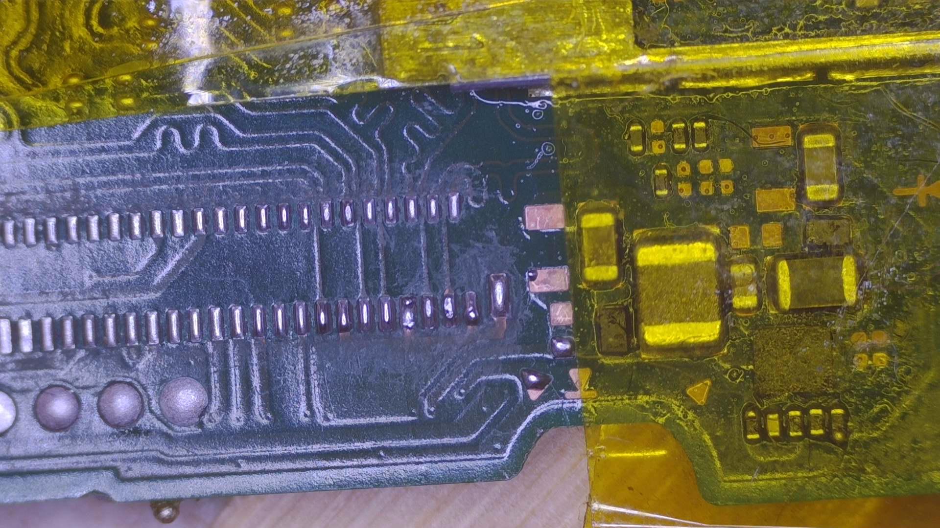
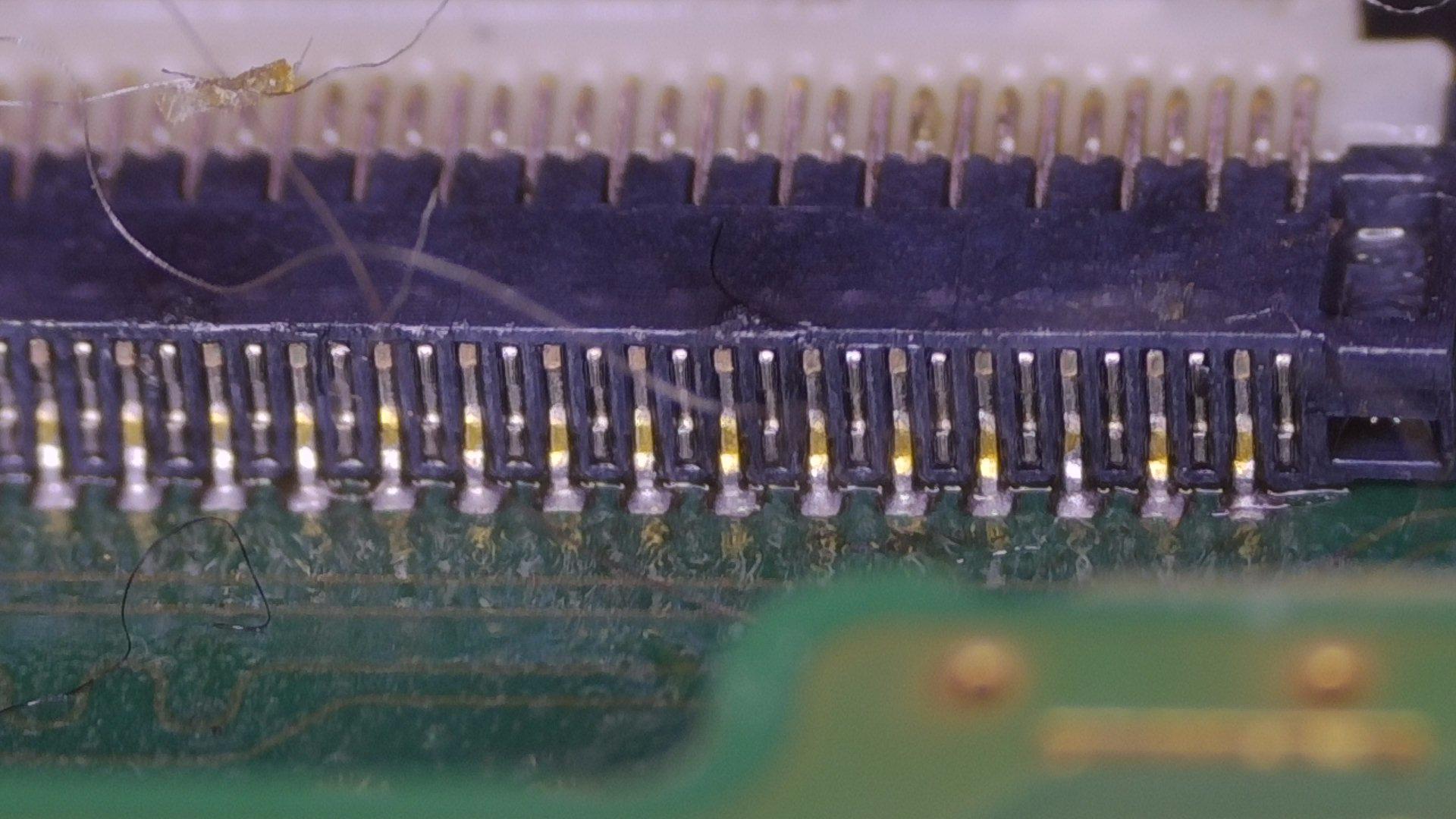
On almost all pins the solder doesn’t seem to be melted and you have cold solder joints. What solder are you using?
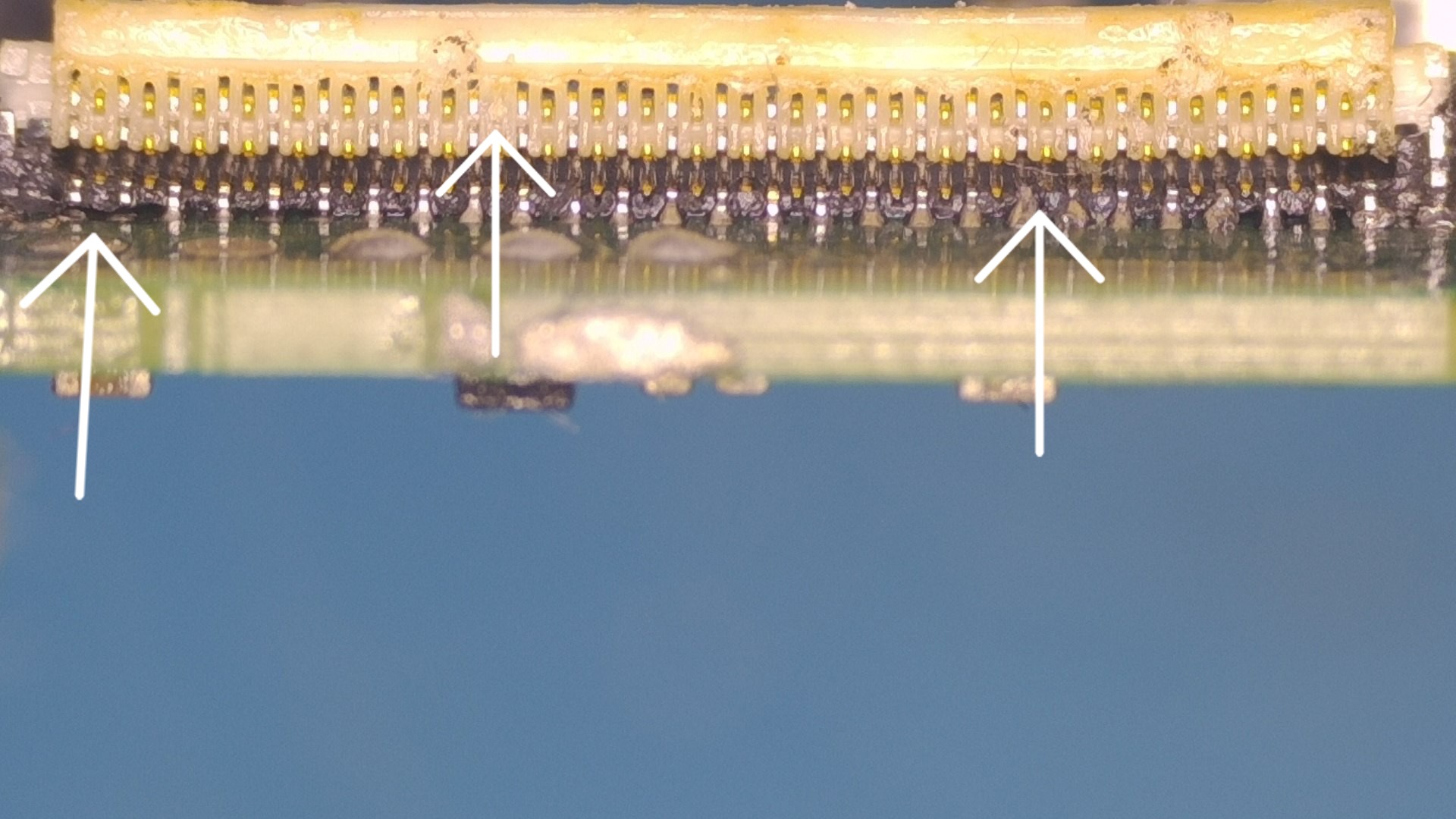
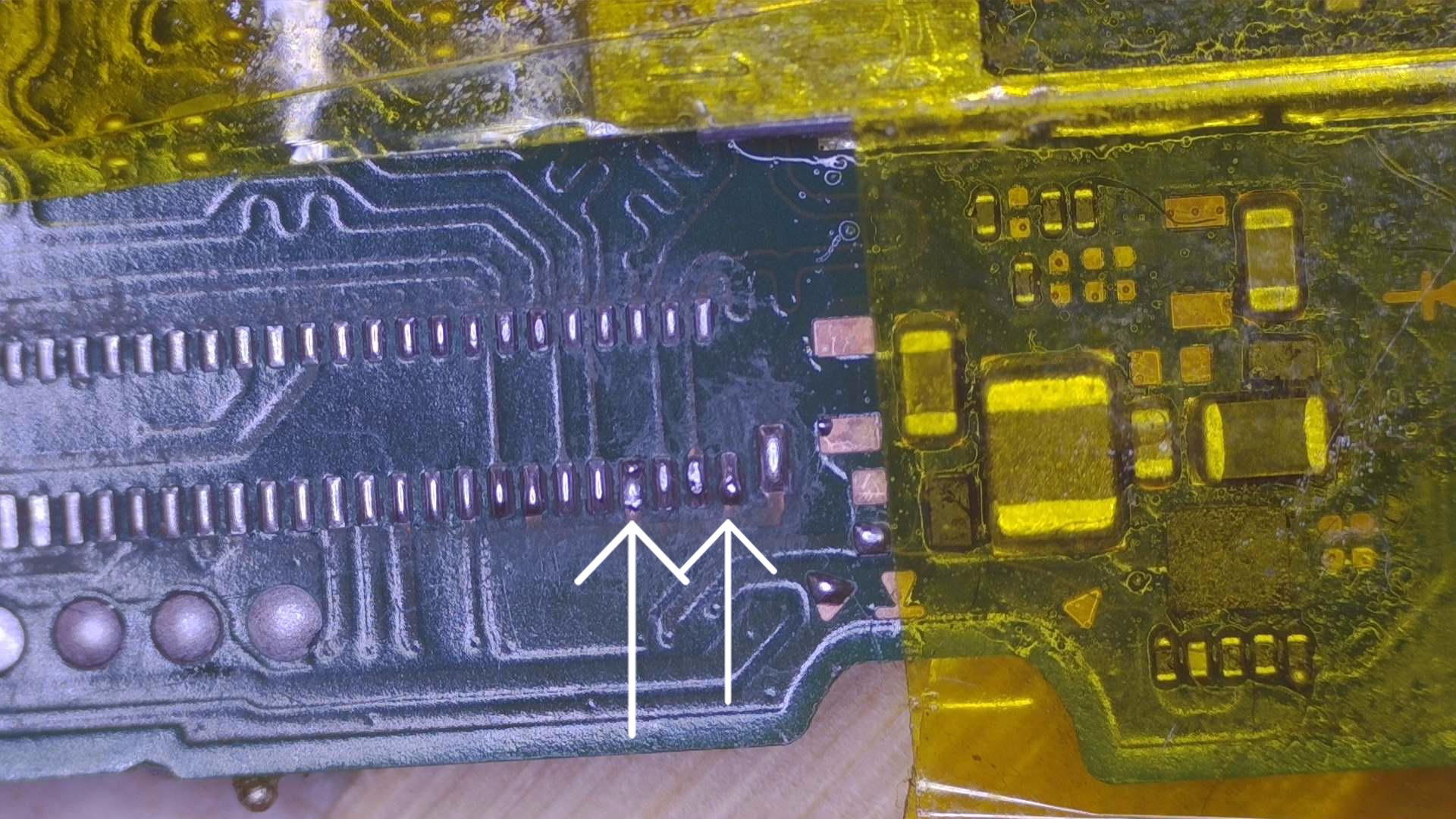
The furthest left arrow several pins aren’t soldered. The middle and right arrow are pins that are missing or damaged. Also, your connector is warped/melted and looks to be bowing up on the edges. The best way to do it is heat it from the bottom of the pcb and cover any components that could be damaged. Including any connectors. I use aluminum tape for BGA and it works great. I set my hot air on 480°C without a nozzle.
I think you said you were trying to melt it from the bottom and we’re able to melt the solder? What hot air station do you have?
Sorry for the bad news. Thecod3r has a great video on how to replace them. Do a YouTube search on “replace lcd connector nintendo switch” and should be the first result about 49 minutes long.
I was struggling to get the darn thing to sit properly, So….
I ended up trying to use the old skool method with just my soldering iron and micro tip….obviously was not a good move.
I will revert back to hot air and try again.
I have a spare connector so let’s hope this one goes on properly.
First things first is to remove, clean and start fresh with some new solder.
**** Note: I was having quite a difficult time trying to get a couple of the pads to take new batch of solder… no matter how much heat I threw at it, the iron would just not wet those pads…
Obviously after a lot of attempts I managed to finally get it to…….any thoughts ideas would be greatly appreciated.
I started off as just a Hobby - something to keep me busy… but as my experience built up on mainly messing around with iPhones / iPads, I found myself helping out with Friends and Family, Friends, Friends of Friends and so on… so started making a business out of it all.
As you can probably tell… I am no Pro and have many more years to be fully qualified in this type of work…but with time I hope to.
My Iron: is a Hakko iron
My Hot air station is an 858D station. (Probably not the greatest but was bought as a gift for me)
I have several size nozzles too.
Solder…
I have several types of solder -
Leaded solder (63 27) (0.3mm & 0.6mm)
Lead Free solder (used extremely rarely as needs a lot of temperate to wet)
Two types Type X series Solder Paste
but I always find these pastes can be quite messy.
I will watch the YouTube and go from there - thank you for your support
You’re welcome for the support! I noticed you said some pads weren’t taking solder no matter how much heat you used. It kind of sounds like those pads may be toast or your hot air station isn’t strong enough. If you haven’t installed the new connector yet, can you get a picture of the pads under a scope with the PCB cleaned up? You may have to get the pictures in sections to get it up close.
It does take a lot of practice, but it also takes a lot of practice with the right equipment. Your current hot air station is good for some things, but I don’t think it’s powerful enough to cut it for this type of work. I had one myself. I use the ATTEN ST-862D and love it and very reasonably priced. I would suggest in upgrading with this hot air station as soon as you can. It will make your life alot easier with practice. I started out on junk PCB’s that had microscopic components and practiced removing the components and connectors and putting them back on.
Let’s see the picture of the pads and we’ll go from there.
Nice, then apply flux and use leaded solder, Mix it with the factory solder on the pads, use a wick to remove All solder, then apply leaded solder again.
If you install the New Connector allign it properl, then apply heat from the bottom. If it moves, realign it until All pads have Bern meltet and the Connector is in the right Spot.
After cool down, check ever pin. If some arent connected, just solder thrm with the Iron.
Yup, what you said. I would however apply some flux and see if you can get rid of these solder bumps. It will allow your connector to sit flat when using hot air.
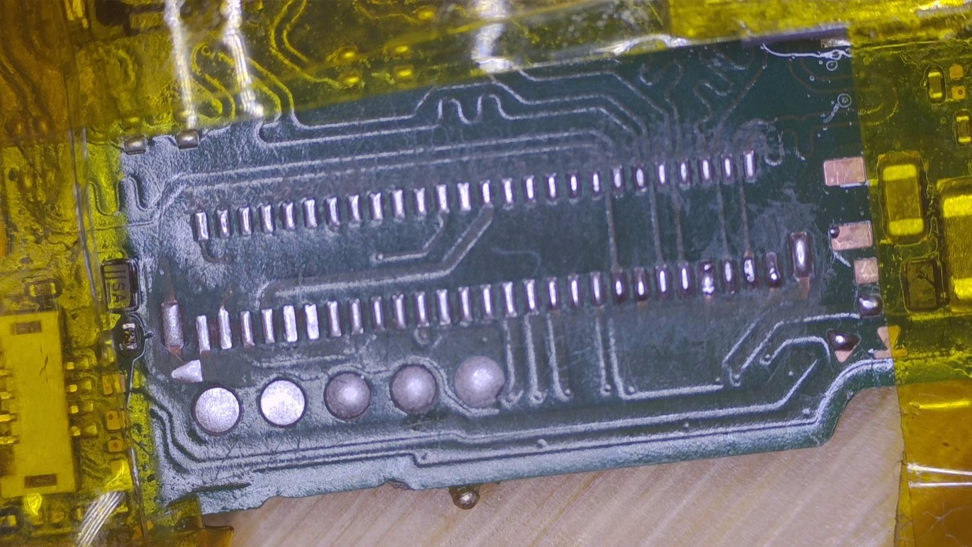
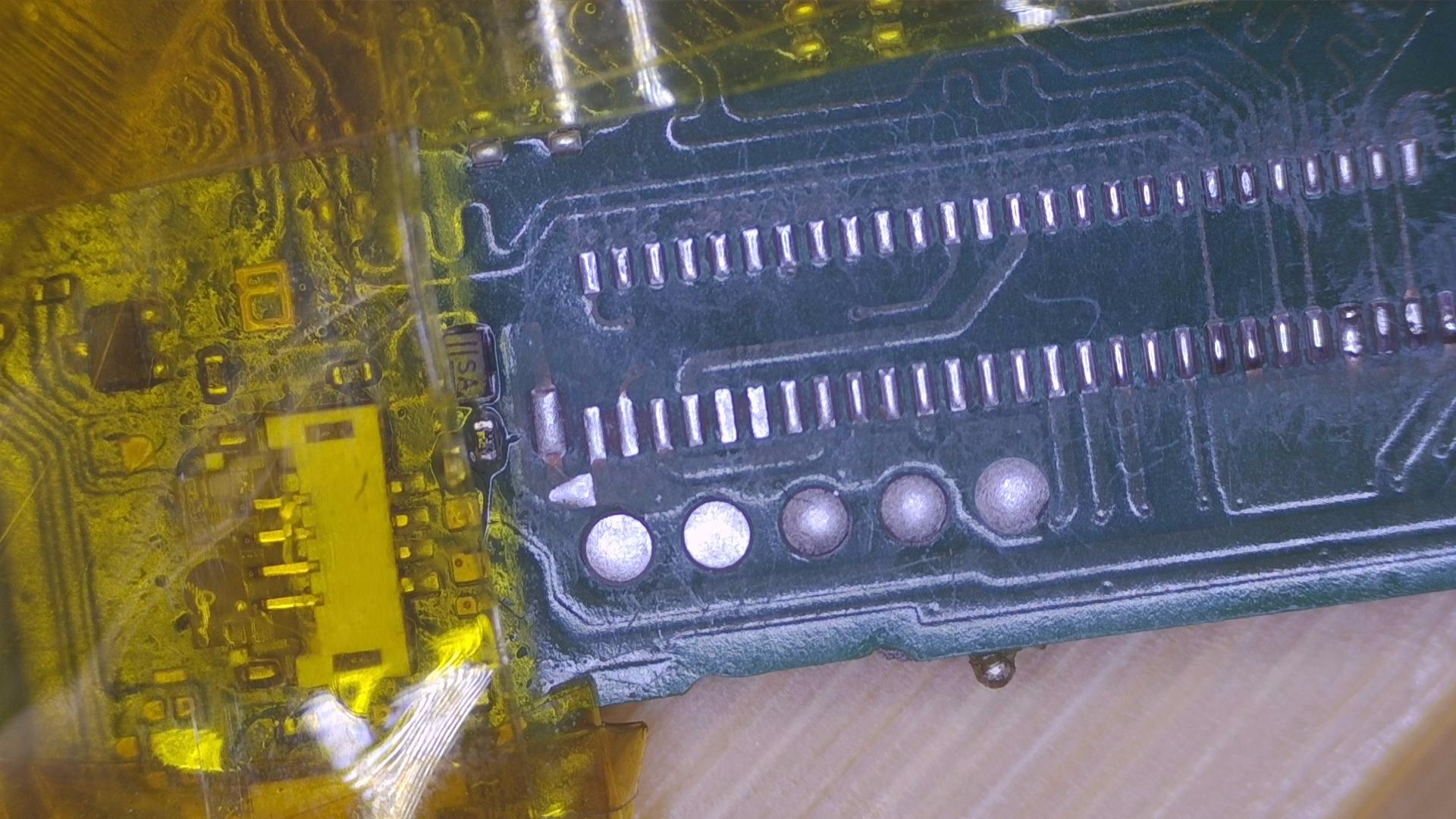
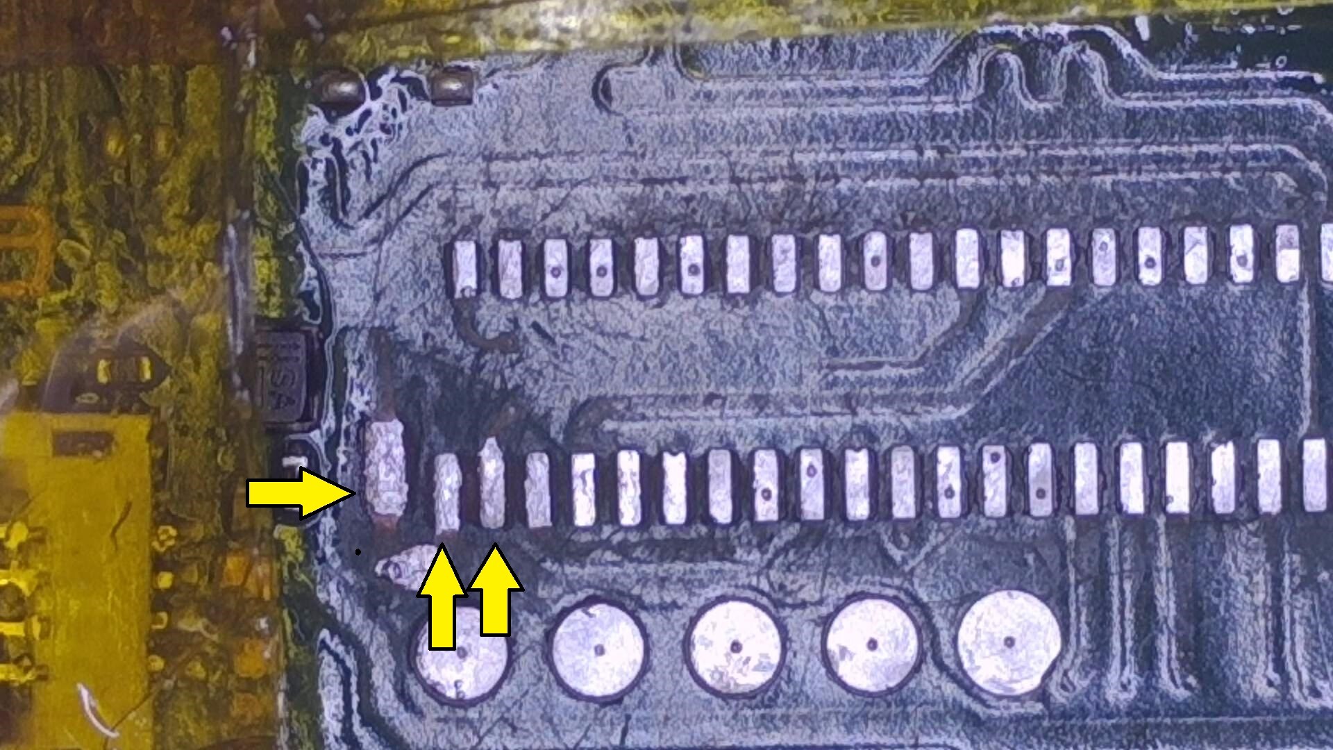
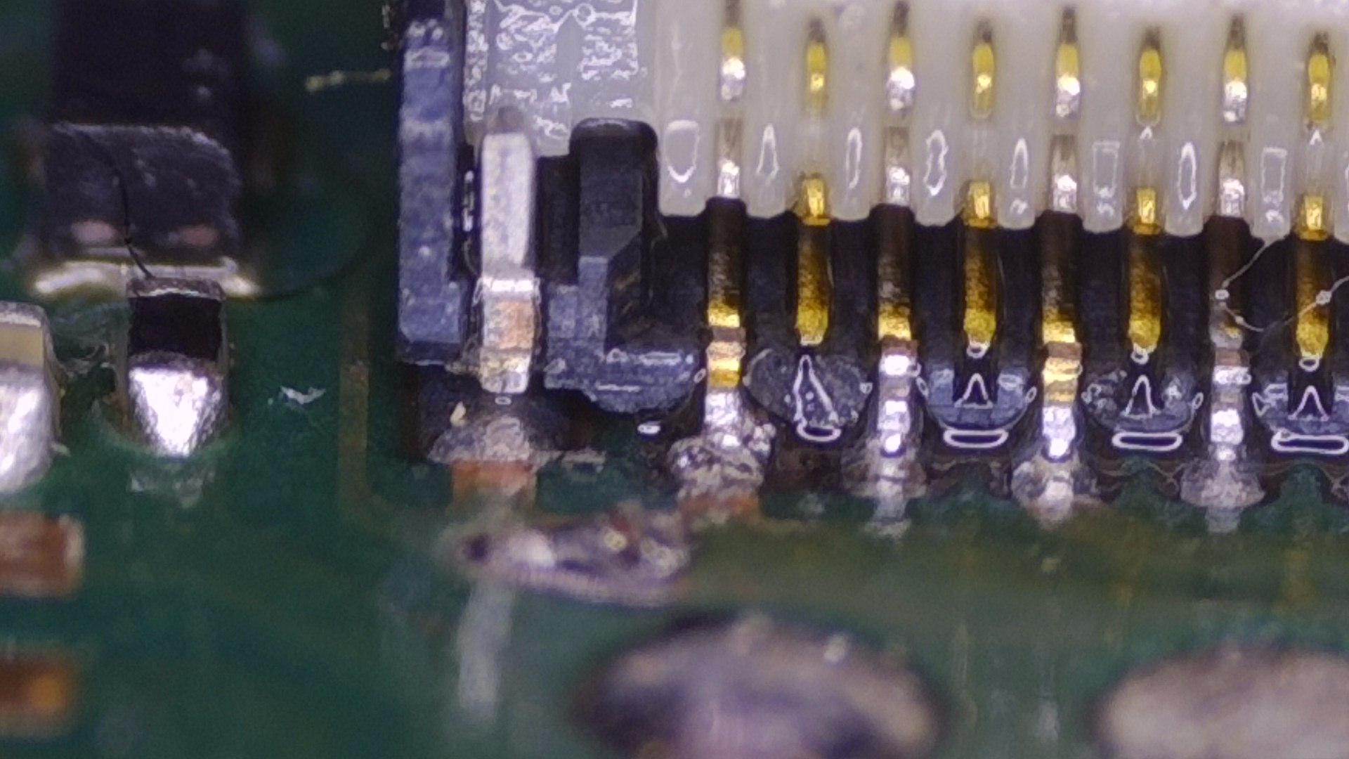
This is the absolute best I can get this board cleaned to. The 3 yellow arrows are the 3 pads I was struggling to wet previously, but I went for a larger iron tip and it seemed to sort the issue.
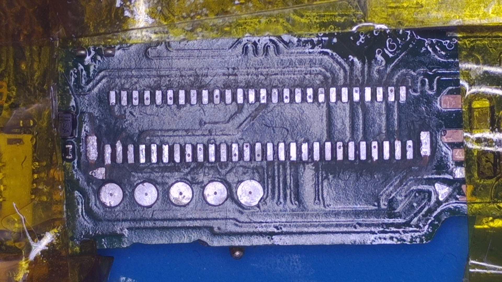
Do these look good enough to receive new leaded solder ready for connector???
The solder is 0.3mm Tin 63 Lead 37… I am able to use this on iPhones no problem justr this switch didnt like it originally
I took a risk…
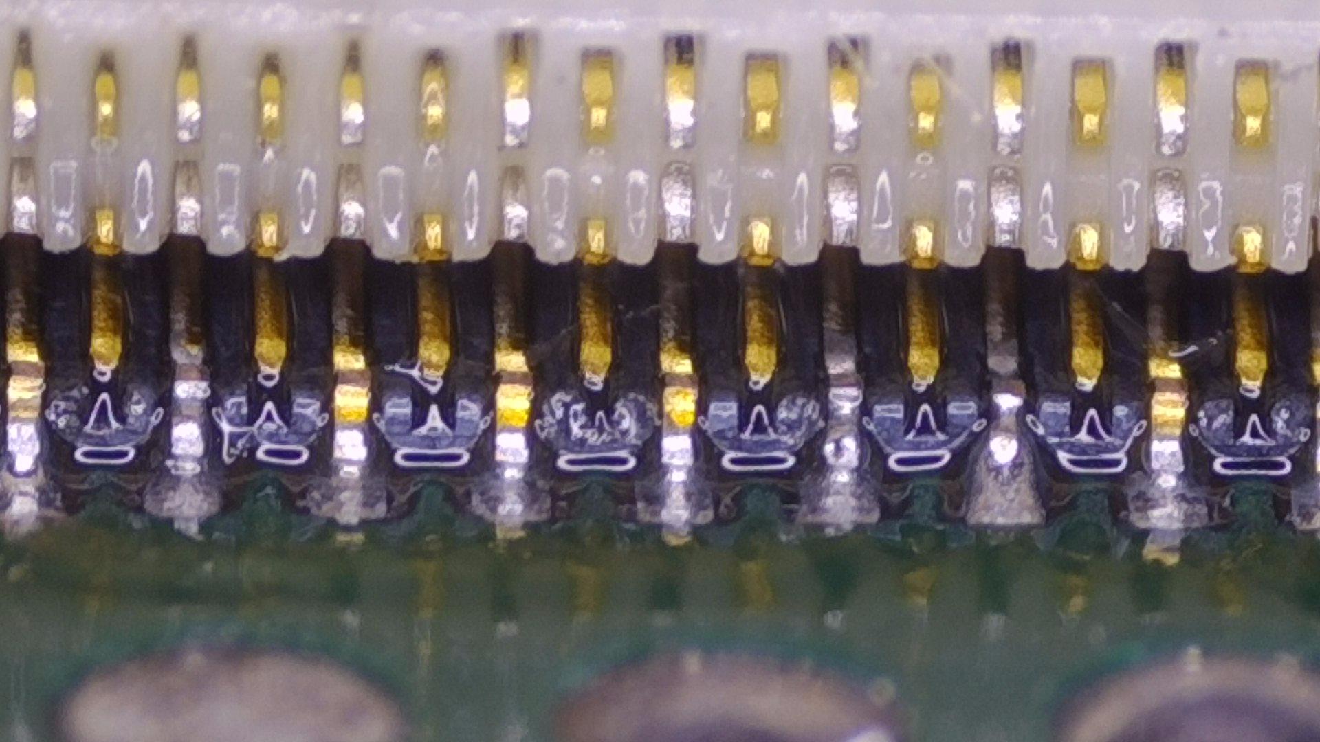
Here are the results (Before flux removal though)
Note: The first and second image are slightly different, 1 is focused in more to 1 side than the other.
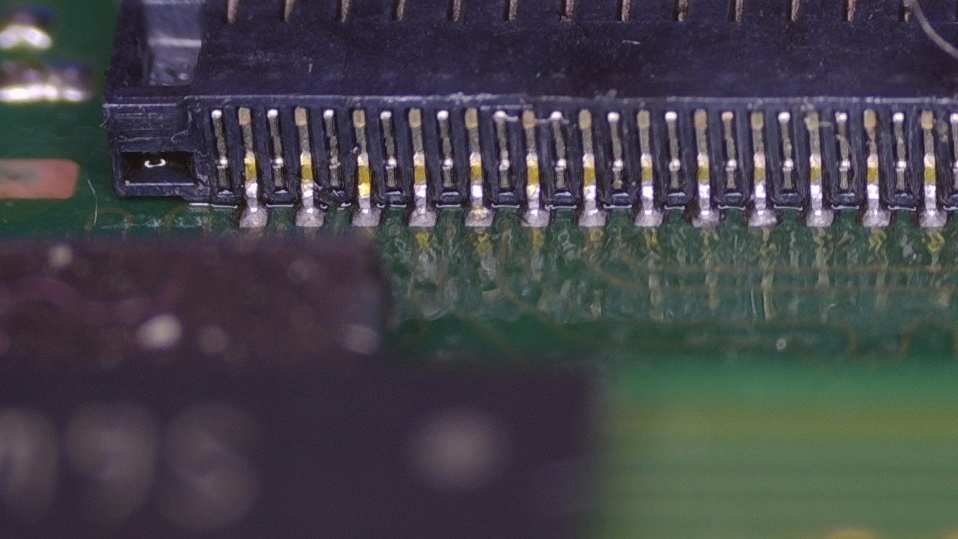
back looks ok, if not canted just slightly, front pins (under the white latch) look a little light on solder to me. Could just be the blurriness though. Best thing you can do is take something to gently push on the legs of the connector. If you see the legs move then the connection is not solid and needs some love with a fine tipped iron or another pass with your hot air station. When i replaced this connector recently i did the initial work with a hot air gun, then added a little more flux and tapped each pin / pad with my iron. Worked a treat, just take caution if you use an iron to not make contact with the plastic
Some Front pins are still golden and there is a chance they arent connected to the pads.
Usr a small Iron to solder them on.
First you can Check with your tweezers if the are solid or not.
@zyrex@coda
Many thanks for your identification on this.
I managed to use a soldering iron and connected these pins.
It is my birthday today so I am no longer at my bench for today. But will return to it tomorrow morning where I can continue my repair.
I will provide some more recent photos for you to take a look at if you can please.
Paul
I am back now from my long enjoyable birthday to this ‘HORRIBLE’ Switch haha
So I connected up the following:
LCD Connector (recently replaced)
eMMC
Backlight connector
Battery
Power Button connector
I power it up and get…
Zilch / Zero / Nothing
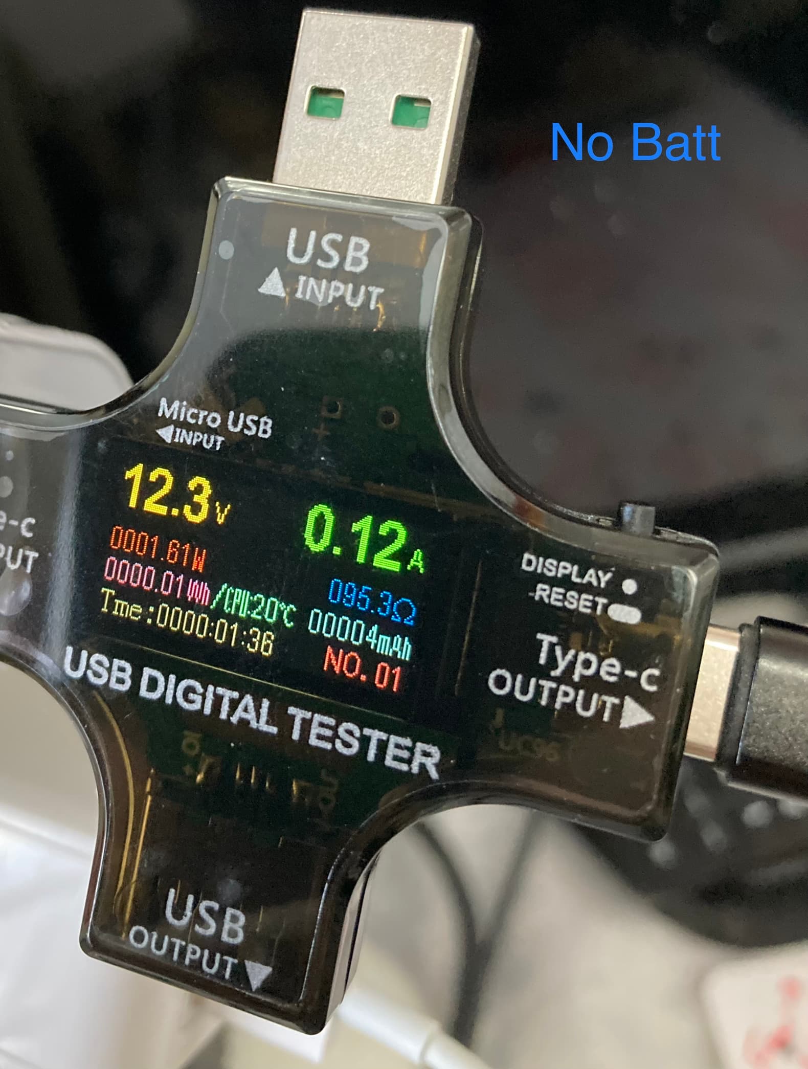
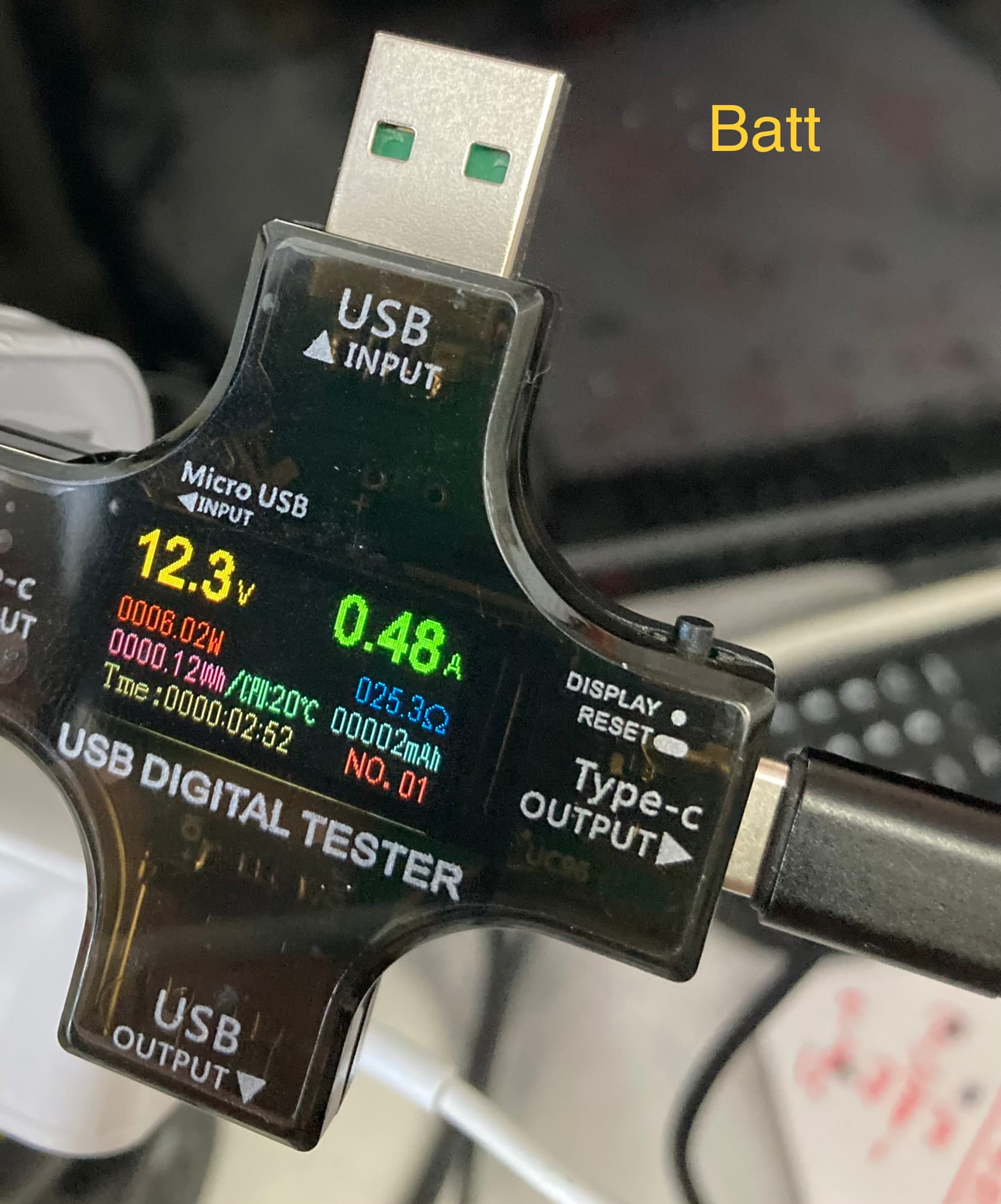
I plug in my USB Tester (Note…I do have a new one being delivered today though- as the current one only has a USB-C Input and USB-A Output) where as the new one will have USB-C Input and USB-C output (so will work with a PD Charger)
For now though… I get:
5.06V
0.469A
10.8 Ohms
2.373W
The CPU is nice and warm though
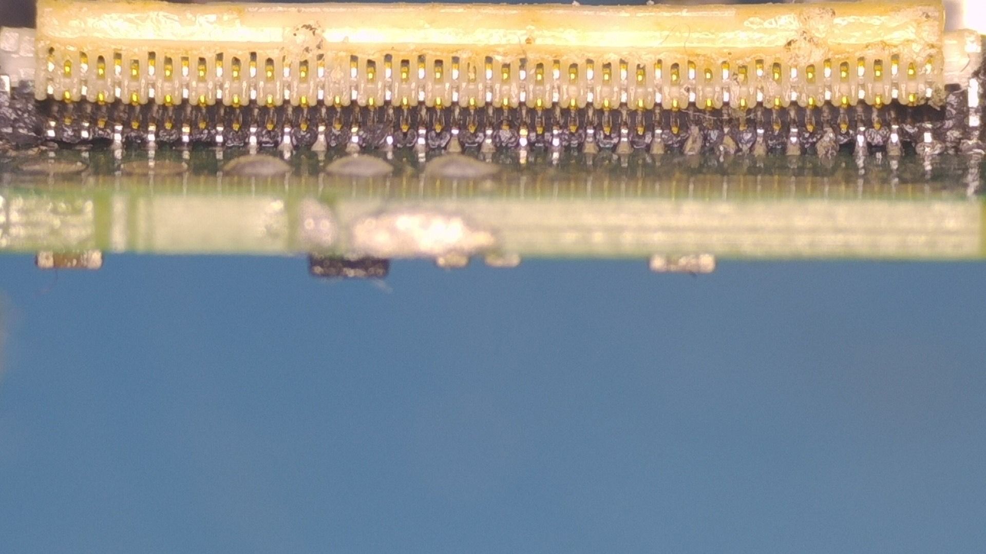
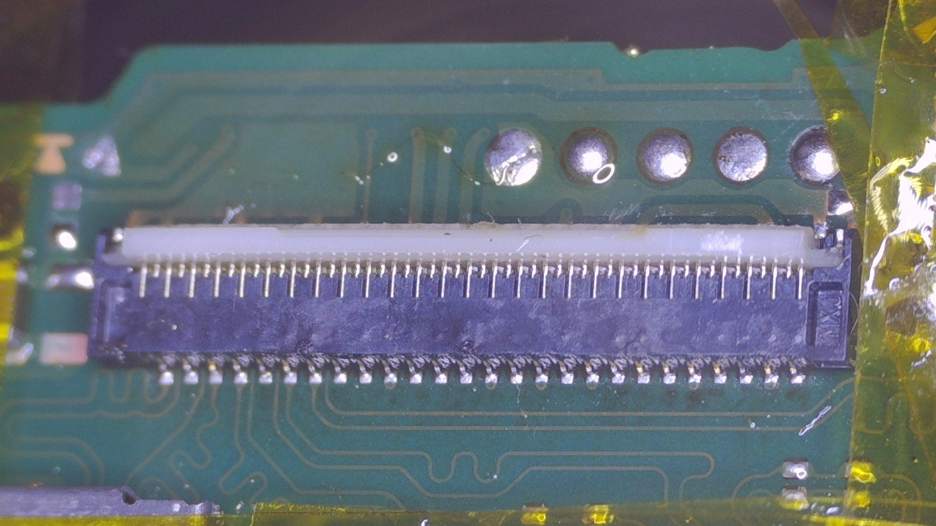
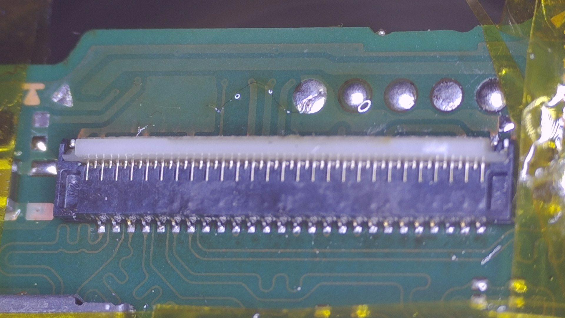
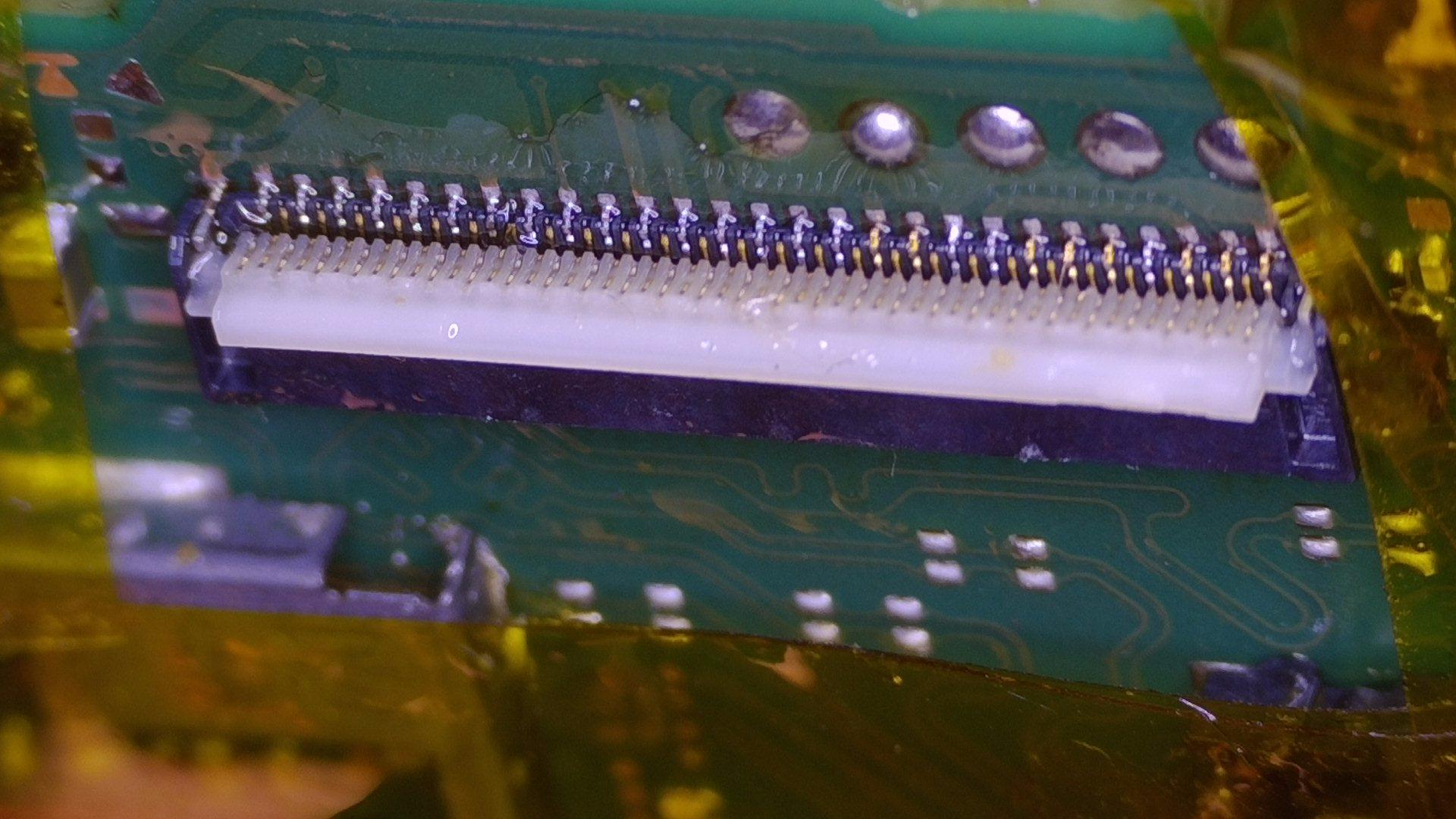
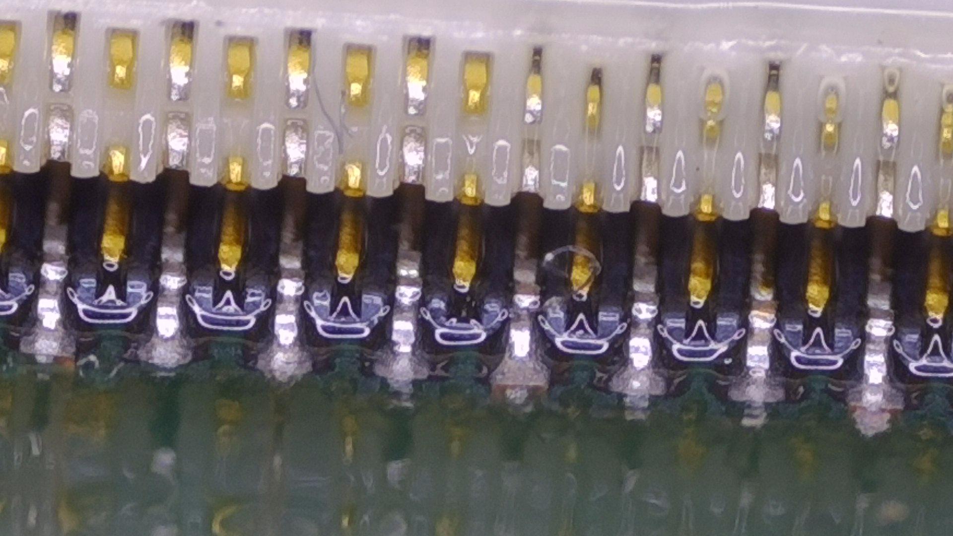
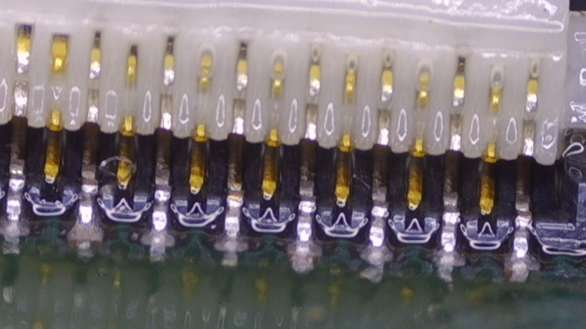
Further pictures as close (although probably could get a little closer if I used a good jig) of back side of connector.
Then following post will display Front side of connector
I would definitely say all the pins are soldered.
Note…
I have ordered a new LCD incase the original short circuit (from the faulty pins) damaged the original screen… BUT I am reluctant to install this new screen if it is going to damage the new LCD…
Any thoughts… I saw before about getting some measurements but unsure where is the best place to touch multimeter probes to pull accurate readings… without a schematic diagram
The solder connections look good, but like mentioned previously you will need to see if any pins move by pressing the side of the pins with your tweezers to be sure.
I think until you get your PD cord and good amp meter the next best thing to do is get the LCD ribbon cable under a microscope and take a picture of the contacts of the ribbon cable. The ribbon cable can become damaged when insterting it into the previously damaged connector. Also, I didn’t see you say if you tried the flashlight test. Hold off on this.
Let’s see the LCD ribbon cable before you do the flashlight test. We don’t want you to damage your nice connector because of a damaged LCD ribbon cable.
regardless of if the pins move or not (or have a connection) the joints all look cold to me (this could also be down to poor quality solder too mind) and you can see the left ground anchor doesn’t appear to have taken to the connector, I would probably give it a secondary reflow from under again, gently tap (but don’t hold) the connector down during reflow
regardless, the lack of high current following prompt to boot implies other issues - I might first check the fuel gauge, M92, USB etc
I have received the new USB-C tester and have the PD charger and PD wire.
I have taken some readings…
a) just eMMC connected
Then b) with Battery & eMMC connected.
I will take a close up of the LCD ribbon cable - but it might not be today or tomorrow now…
From what I could see though the cable did look in good condition- although a very very slight kink in one bit, but nothing that should cause any issue.
Kind regards
Paul