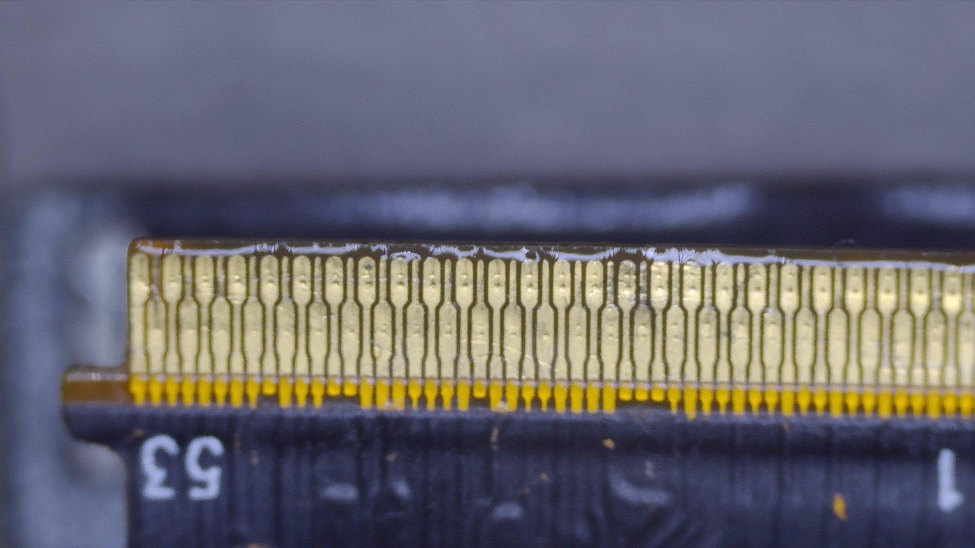
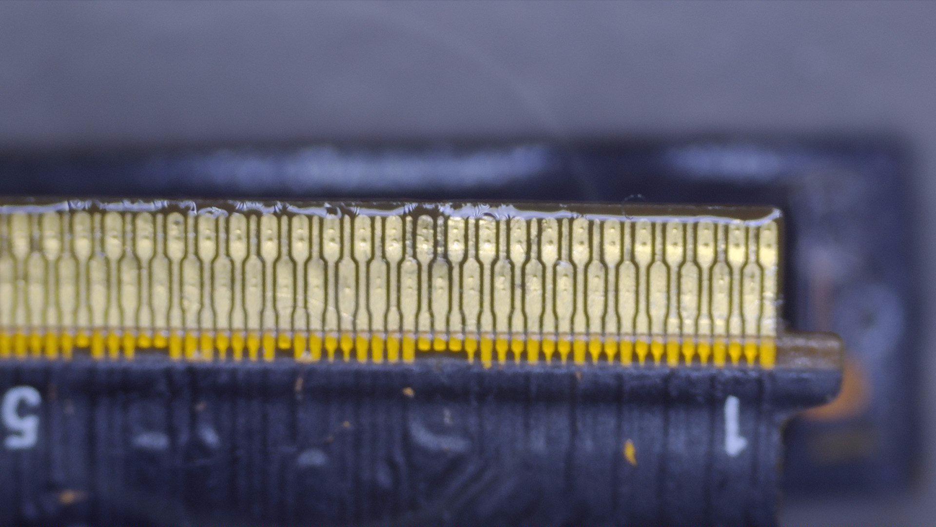
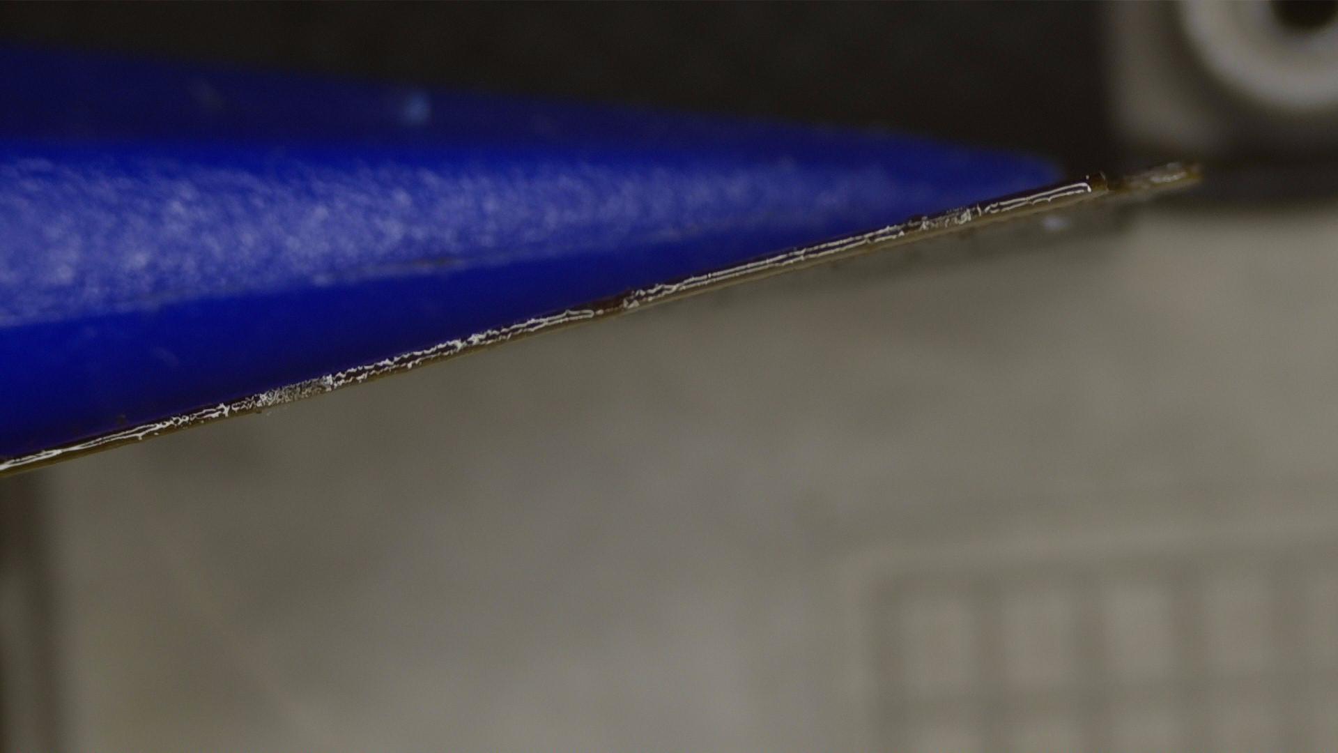
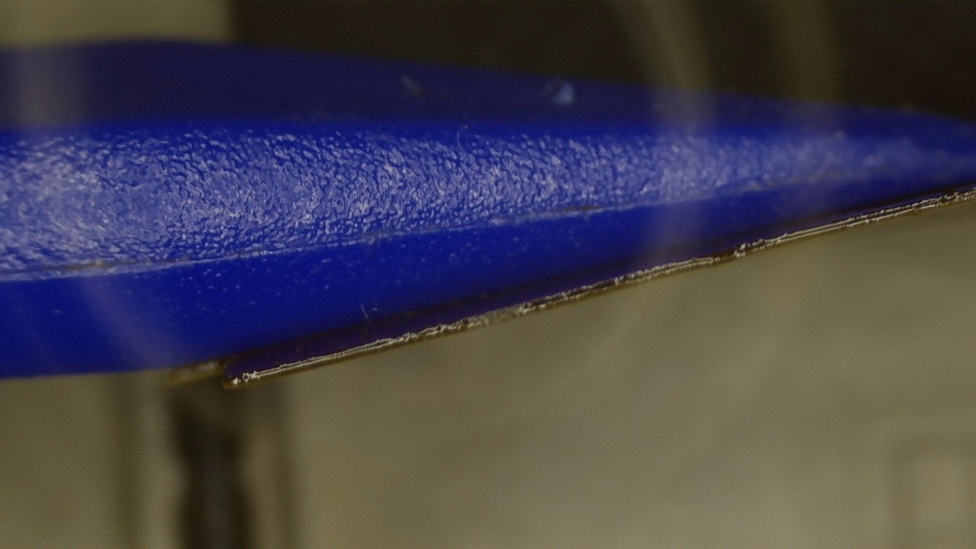
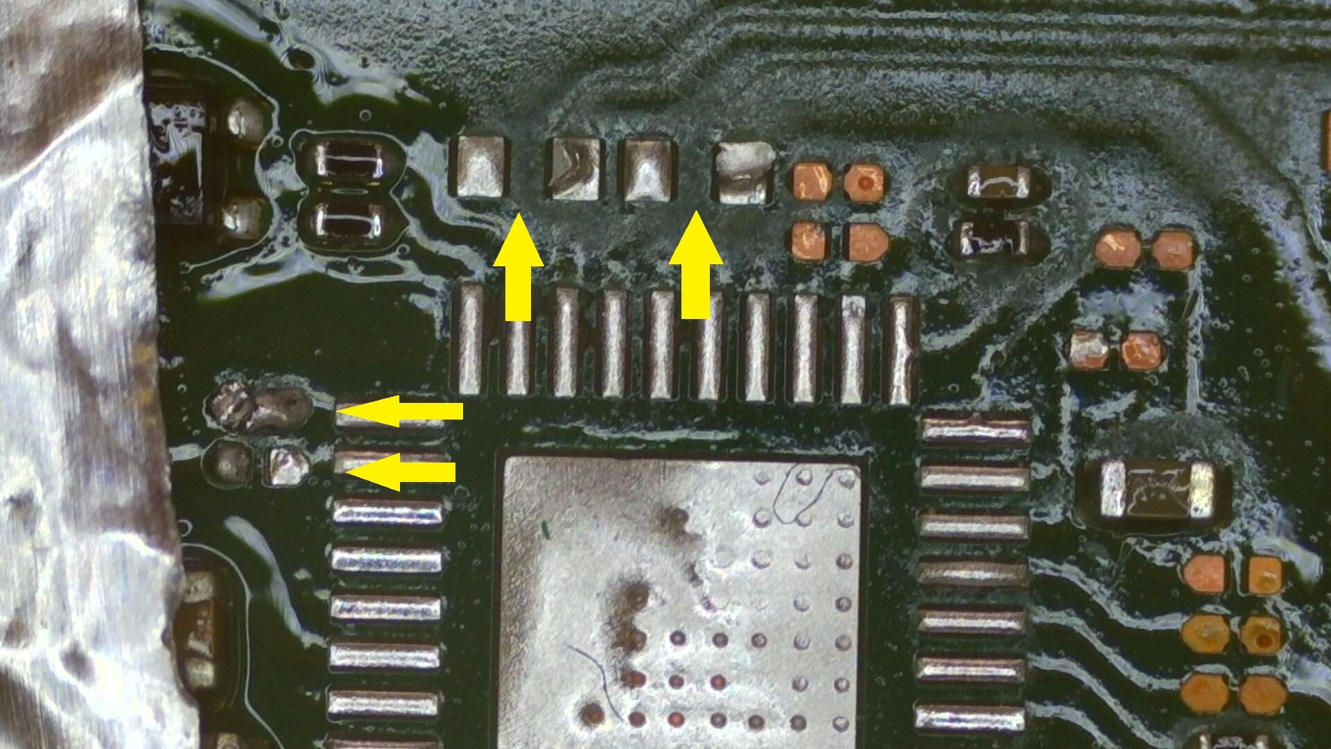
Okay so I managed to squeeze a few extra minutes in to take some of the LCD ribbon cable
Although there is a very minute slight kink in pin 11 - 12 (working right to left), I dont think this would cause any issue…I have seen much worse and they have still operated within smartphones before.
From All Photos I assume your LCD will work, but as @Severence said, Maybe give it another reflow.
But regardloss of your LCD Connector, the switch should Boot and charges with over 1A. So you have a problem here.
I would remove the M92 completelly and then turn the console on with the Power Button and a charged battery.
If it will Boot and Shows an error on the screen, you know the fault is your M92.
Otherwise it could also be the fuel gauge. Also check the USB for bent or broken pins.
M92 will not lift off.
I have read that people heat from the underside but… there is another IC directly underneath but unsure what one that is.
I have tried adding low melt solder paste, plenty of flux, used iron with fine tip to mix low temp solder and then applied steady even heat but she won’t lift off still.
Obviously I am aware that my hot air station is a little on the low power side but even still with cranking temperature up, I still get no joy
One of my friends has given me a heat plate that is made from one of those PTC heaters and just gets hotter and hotter. Not even sure what temperature they get too either.
Just wonder if that would help, and what precautions (apart from burning myself) would I need to follow?
Any thoughts please?
Paul
@Insomniac
I didn’t want to damage any other components around the M92.
I started it at 200 then built up to 420 with airflow of about 5 or 6 (out of 8)
Note: I do have good heat shielding around the entire board though, using Aluminium foil tape…that I had read is one of the best methods apart from the ceramic stuff you can buy
So you reckon crank it up to 480 degs - okay I can try that now.
@Insomniac
Oh boy…I followed your 480 degs… well that did the trick but now I have a few (total of 4) components that were around the M92 which blew across the board… thinking Airflow was too high.
I really need to use my old test board to get things working how I want them too… especially with NON Apple devices (I know exactly what setting for them but its TOTALLY different for this Switch,
I’ve located them but need to know which ones go where???
Note: I can see where they need to be replaced but need to make sure the correct value goes back in its right spot…
2 x Caps
2 x (what I believe to be) Resistors
Paul
I only Mix the factory solder with my leaded solder, after I removed the Chip.
I have no Problem removing M92 from the top with the factory solder on.
Make sure to use a good Heat Gun, Best you can get is the Atten D862, the other 861 from Best or some other nockoff Brands also good.
I use around 460c and 50% airflow with my Atten. If the solder is melted you can increased the distance to the board, just to keep it warm but dont blow anything away.
@Insomniac - have you had any joy with those values for me please?
@zyrex - Okay so I will be looking at investing into an 862 at some point.
I have so many nozzles though and it looks like these aren’t compatible with the one I have now…but it will be in the near future.
Just had my birthday so have to wait a little while
Paul
I dont know, my parts board has already had them stolen and I get nothing useful with them in circuit. They are bypass caps though, so I would expect it to boot without them.
@jkyoho
Thank you so much for those values. @Insomniac thank you also for your response in regards to the resistor values.
It would be amazing if anybody actually had the schematic that they would kindly share with me for this Switch.
I will be returning them to there rightful home shortly, and will let you all know how I get on with that task….
Then it’s testing time since the M92 is off
M92 removed and all SMD have been put back in their correct location.
The only things connected are:
LCD (with a reflow carried out again),
Push Button,
Battery (which I am unsure has any charge left since I have been testing with it)
Plug in USB tester and it’s now pulling no amps at all…
No display on screen either still.
Is this how it should be with M92 removed?
If so what is my next step
it won’t charge without the M92 IC (USB management IC)
I’d probably check the battery voltage to get a rough idea of capacity, if it’s overly low I’d charge it up manually and after attempt to prompt the console to boot with the power button
@Severence
This may be a silly question… but how can I manually charge the battery if I can’t get any good readings from the Switch and know if its actually power / charging etc.
I made up a female board for connecting up the battery to a PSU, if you don’t have one you can push some fine fly leads into the battey positive and negative terminal and charge via a PSU (or dedicated Li-Ion/Po charger) - on a PSU you set the votlage limit and monitor current draw (to monitor charge) and on a dedicated charger it’ll take care of everything until it’s full