@Severence
Ooooh now I get your response…
There you go you see, yet another route I thought was good but in fact is another dead end.
I will do some more serious researching again #freshstart I think.
@Severence
Ooooh now I get your response…
There you go you see, yet another route I thought was good but in fact is another dead end.
I will do some more serious researching again #freshstart I think.
Any youtubers you can recommend for us, @Severence? 
Hmm 
There’s none that will represent my repair methodology here on this forum (at least I don’t know of any) but here’s a list of a few youtubers I like and I’ll address some of the caveats. I’ll try and put them in some sort of order from beginner up kind of
covers very basic fundamentals of electronics, simple stuff, but a lot of people skip right on over to the repair end without even understanding the basics
Nice guy, funny
Mymatevince, even though he his learning himself, he always engages his brain
She is very good at what she does, as in the practical work, but just note she has a few fundamental misunderstandings on the theory side of things and still diagnosis things in a somwhat dated way, but if your a beginner this is great. Anyone else and you might find the manner in which she talks (like your a child) a little annoying… or like your your watching an episode of sesame street 
pretty much can’t fault him, he will commit one or two cardinal sins (mentioned earlier) but he will almost always admit to it (do as I say not as I do) . His work is typically “janitorial” but you can gain somegood info in and amongst it.
You’ve got Paul from Rossmann repair, he’s pretty on point too and of course EEVBlog…I think that’s my lot
@jkyoho
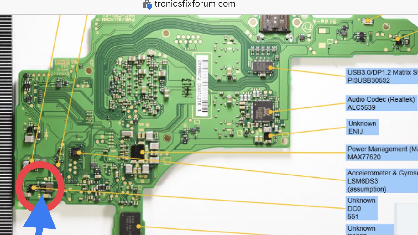
I’ve just re-read your response… I found that image on Google and thought it was the M92 section…but realise you was trying to tell me that it was the BQ section.
I am needing a diode mode image of the M92 so that I can then circle which CAP is missing and then get the correct value.
@Severence
Many thanks for that extra information… I did start to watch some of these YT and spotted that My Mate VINCE does seem to use the squeeze error but I do like his videos…
I used to watch Jessica’s iPad Rehab when I started repairing iPhones…
Paul Daniels is very handy for my MacBook that I need to sort out at some point

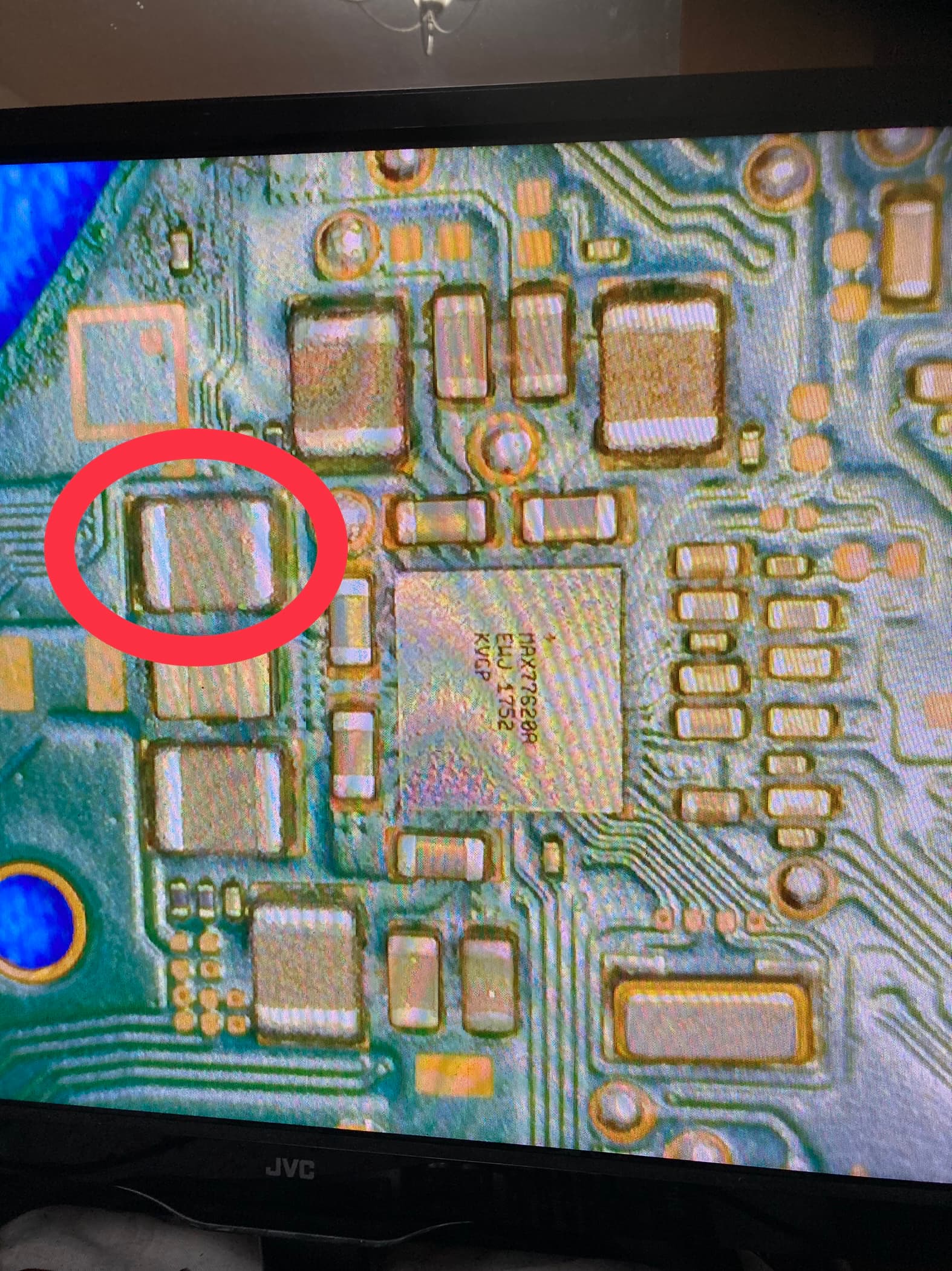
Circled in blue - I believe it is VBUS - GND so is an important component.
Also going through some CAP tests with Continuity mode…
(Circled in red)
this Inductor has the same ohm both sides (will be more accurate when I get my UNI-T multimeter) but both sides are reading 40.2ohms - is this normal
Yes, you should get the same reading on both sizes of the inductors, and 40 ohms seems about right. for that one.
@Insomniac
Thank you for that information- so that would seem that all my Caps / inductors are good then
@jkyoho
An joy with the missing Cap circled in blue please
0.01uF_0201_20v
reference on Pg.26
@jkyoho
Thank you for that information… the Datasheet is extremely useful.
@Severence @Insomniac @zyrex
Not sure if I have asked this one before… but should a Diode NOT have one side which is going to Ground (000.1 ohms) like I have…or this normal
Diode mode = 0.105v one side and 0.000v the other side
The diode I am talking about is on Side-B; opposite side to where PMIC is situated
The fact your still taking diode mode readings suggests to me you may not have read/searched the forum as much as you should have… what are you even measuuring first of all (apoligies if I’ve missed it?) but generally speaking it’s pointless
this is meaningless which I’ve talked about many times…search the forum ![]()
@Severence
My bad… it was just an observation as I was checking all the caps for shorts and going through various forums to try and suss this switch out and that’s when I came across the diode.
I am still waiting delivery of my new multimeter so just thought in the meantime I would run through the caps again for any shorts and that’s when I found the diode.
I generally don’t use Diode mode really because it’s normally only best suited for testing diodes (which is exactly what I was testing)
As I’ve touched on before, aside from a few fringe situations, in circuit diode mode readings are largely useless (yes even for measuring diodes specifically in circuit) - now on the other hand if you were measuring said diode out of circuit then that’s a differen’t matter. Also I’m not entirely sure which diode your talking about ayway? (picture might help) but tbh it seems like your just randomly measuring stuff on the board, which if that’s the case, it will do you no good and you’ll just continue in circles ![]()
As I touched on earlier, I think your best bet is getting a replacement board which works, then you not only have that as a point of reference but you also have a board for your friend in the event you can’t fix the existing one
@Severence
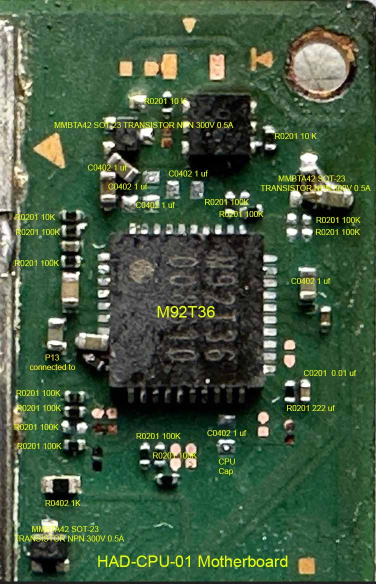
This is the said diode.
As I said previously though I am not one for using diode mode normally and only switched to diode mode once I spotted a resistance to ground issue.
I decided to take another look at this Switch late yesterday… and pretty sure I was following the Boardview circuit path from Backlight IC and it lead me to this area with said Diode in circuit.
It’s Sunday today so generally don’t sit at my bench but if I get a few spare minutes I will go back to what I was doing yesterday and then can trace back.
Will be in touch again a little later
For now (here is the image)
@Severence
Ignore the previous… I have just gone and taken another look at the Boardview and seems I followed a wrong path.
That diode and area has nothing to do with Backlight IC
Note to self… I should always refer back to my old Human Factors training from previous job…Don’t work when fatigued because errors are more than possible
@Severence
My new multimeter has arrived finally…
If I order a new Switch PCB board what do I need to transfer so that my customers data etc is still present.
I have spent far too long on it now…
My solder is (as you advised) cheaper Chinese type and not reflowing properly.
I can’t seem to find the same size core though in Mouser so that’s not helpful because the solder is too big for the job in hand.
Also my reflow hot air gun is not up to scratch either….
I have ordered a broken switch board to practice with as well
This is a bit complex… I believe you can transfer the game saves… I’m not so sure about the downloaded games mind… to do so you’d open/mount the EMMC and with the correct keys in conjunction with a tool like NXNandmanager you’d decrypt the data and transer the saves onto the other EMMC (bear in mind both would have to be unpatched here). Tbh as this is a bit of a headache I’d just write the data off, especially if he has an online Nintendo subscribtion which I think backs saves up in “the cloud”
The Chip quick stuff on Mouser is in imperial (american company) Last I checked you could get 0.8 or 0.5mm which is more than small enough for most jobs.
![]()