Hi guys, I just started repairing switch so i’m here to ask your help.
I got a switch that works well with a good battery, but doesn’t charge.
imgur(dot)com/a/l1mnPu7
I tested these blue pins of the charging port (battery disconnected) but i get ~ 0.4V-0.7V on one side, ~ 2V-3V on the other side. But sometimes, at random, i got the 15V on the pins, up to the fuse etc. I got no shorts around the M92T and BQ. Is it the usb port? Any ideas?
If good then connect battery and check voltage on pins 5 and 6 (from memory) on M9 IC should be approx 3.4V
If good then looks more likely to be the BQ chip, disconnect battery/power and check for shorts on the surrounding caps… though it doesn’t always fail short
As I said, I don’t even have 5V on the connector pins. Now for example it stays on 0V, and I got of course nothing through the board. With battery connected I got ~3.4V around the BQ. Could be the usb port?
Ok so, I’m using a Nintendo charger and now I got 0V on the pins.
I tried connecting the switch to the PC (5V output) and I got 5V on connector pins, up to fuse and ~3.4V on pin 5-6 on M9 IC.
Around BQ, with battery connected, I have this: imgur(dot)com/a/UBILg1i
When I turn on the switch, with a charged battery, it says “Impossible to charge” (not the exact text).
If the usb c port looks fine, I would connect the Switch to a pc and try to get it visible in TegraRCMGui. If the Switch shows up on TegraRCMGui and stays during moving the cable, I would assume that the usb c port is at the basic function ok.
The Nintendo charger needs to speek with the M92T36 over the cc line before suppling 15-17 V.
btw Calvin your diagrams are awesome, if you would like my board outlines from fusion 360 and a half hearted attempt with a few components populated board view/3D models, just PM me, also plenty of photo overlayed diagrams which you can apply to your own files if you want them
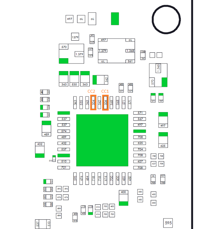
I take measurement in diode mode, red probe on ground, and on the back of the board (side A)
the CC1 is ~0.520V but CC2 is ~0.725V, unlike the reference image.
Here: imgur(dot)com/a/p9JFmXr
The other measurements seems correct
Also, I found this resistor that seems shorted to ground on both sides. imgur(dot)com/a/1VuD3LE (Edit: Ok maybe it’s normal)
It’s very random. At the moment, with charger and battery connected, I have:
15V Nintendo Charger: Side 1: Vbus: Sometimes 0.03V, sometimes If I disconnect and reconnect battery it fluctuates between 2.3V-3.4V, or 1V-2V CC1: 0.01V or 0.56V-0.57V when Vbus fluctuate CC2: 2.76V if stable, or 1.9V-2.7V with fluctuations. Side 2: Vbus: 5.34V CC1: 0.11V CC2: 4.34V or 2.7V
5V Charger: Side 1: Vbus: 5.02V CC1: 0.01V CC2: 4.13V or 2.30V Side 2: Vbus: 5.02V CC1: 0.06V or 4.64V with little fluctuations. CC2: 4.12V or 2.18V
I… don’t know. It’s totally random lol
Edit: With the 5V charger, when i got the 4.65V on the CC1, it charges at 1.7 A
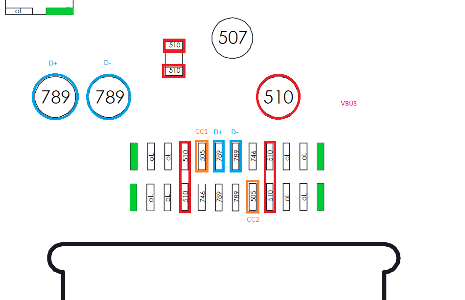
I would inspect the usb c port. Inside for loose or dissarranged contacts and the visible row of pins for bad solder connections. The four vbus lines (blue marking on your first link) are all at one line, so it is normaly not possible to get different readings.
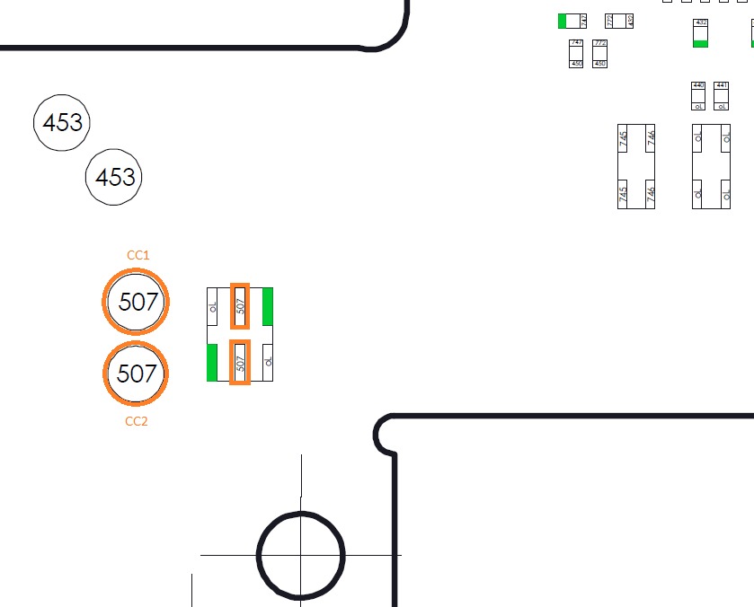
On side A is a little esd protection ic. I don t think that it could be the problem, because if the diodes in the esd protection fails they usually grounding the line, which cause normaly 0mV in diode mode reading. To be sure, I would desolder the six legged ic for a quick test before replacing the M92T36.
Unless my eyes are deceiving me it would appear that there may have been liquid in the USB area at some point or that the USB connector has been replaced at some point and what I’m seeing is actually flux residue. If the contacts inside look good to you, you might try a gentle scrub and then giving it a shot of contact cleaner (or WD40) and plugging a disconnected USB cable in and out repeatedly
This might trackback to what i said in another topic about repair shops/people incorrectly soldering the USB from above and the solder is cold. Or i could be completely wrong and it’s simply corrosion inside the connector
Thanks guys, I’ll try to inspect and clean the usb.
Right now, with the 5V charger is all ok.
With the 15V charger it works only in one way, and it’s charging at 0.35A. Still can be the usb?
I also tried to do this. I put the Switch in RCM mode and connected to TegraRCMgui, it’s recognized and it stays connected moving the cable. So i don’t know if it’s the usb or not.