Sorry for the lare response just had a chance to do some more readings although i still haven’t managed to find where 3V3PDR, and SYS are located below is the ic i believe with readings
I’m going to assume this is ohms, Boot CPU rail, Mariko, All good This confirms to me (together with your previous readings) that you didn’t/haven’t shorted out the caps on the SoC
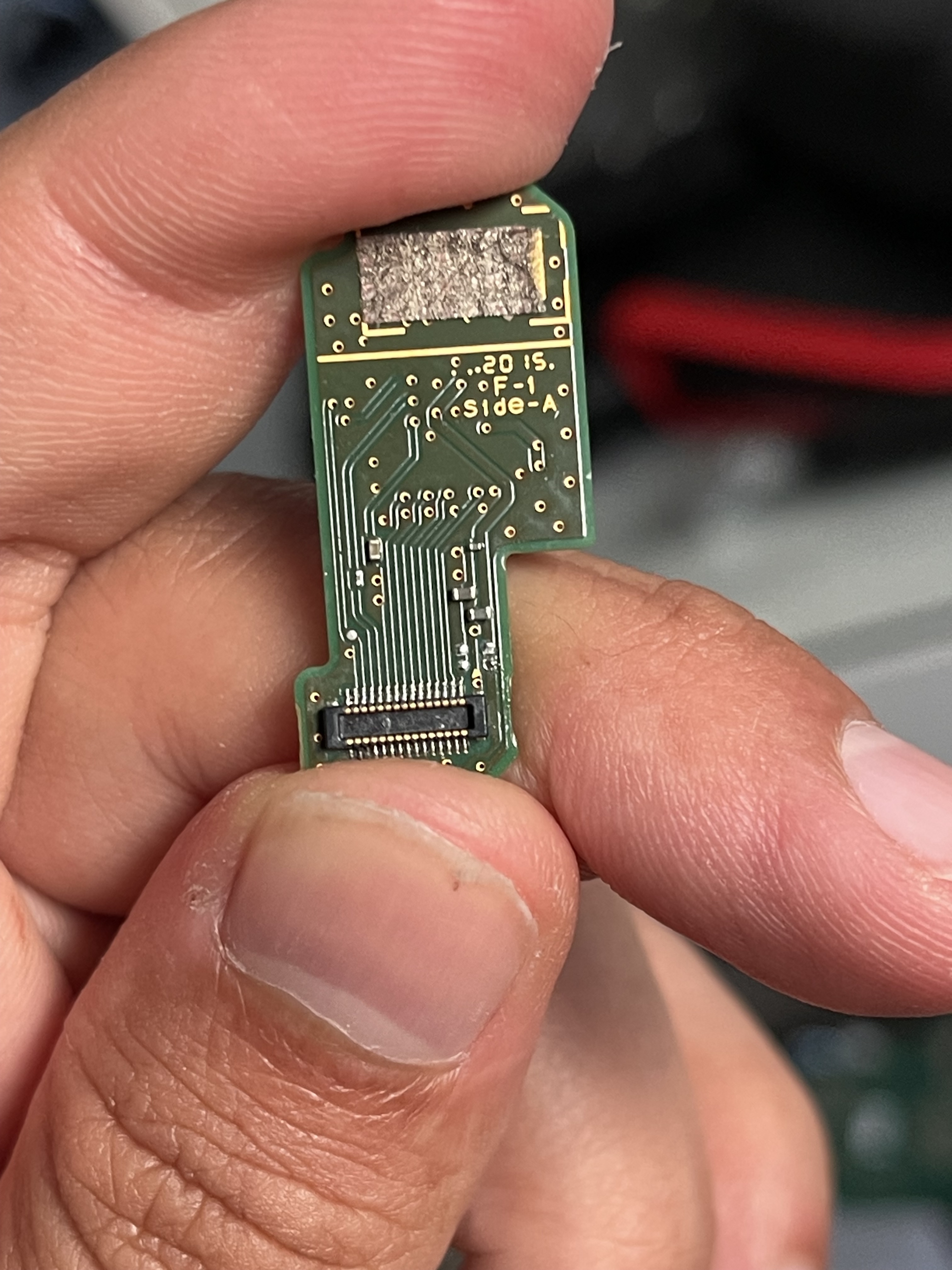
K we’ve got two rails in one here. (one is 1V8PDR an EMMC rail amongst other things) if this is in ohms (again, I really need you to know this yourself and provide the units, for all I know this is metres, miles, pints - In all seriousness, just watch a few vids on how to use a manual ranging meter to measure resistors, I think it will help you ) if it’s ohms (I wan’t you to really make sure of this first though) this is your problem or subsequent to the primary problem. I’ll wait for your 3V3PDR and SYS reading. (as mentioned, big 2R2 coil next to the BQ IC - it was in your previous images [C5689-B5-C-3356-4776-8622-A8-FB5238-E569 hosted at ImgBB — ImgBB]. For 3V3PDR - take your pick, at 3.3V line on EMMC / going to EMMC, biggest cap nearest PI3 IC etc etc) before detailing next steps and confirming if EMMC is to blame.
You should absolutely get a reading, unless your ram has popped off the board try again I’m going off the top of my head here, I think on Mariko it’s something like 170 to 250 ish ohms is in the realm of good here… though don’t quote me on that.
Pretty sure this is 1V35PDR, from memory I don’t think is should be this low. Can someone confirm this for me if you have a mariko board handy? (I think it would ordinarily be something like 130K or into the mohms) @Calvin any idea?
This one should definately not be this low.
So those two rails are the real problem here. (I’ll wait for someone to verify what I mentioned above) but assuming I’m correct, then the likely cause is going to be whatever IC has these rails in common, and that would be the main PMIC or the SoC. I guess you could pull the indcutors for the rails in question and see which side represent the shorts to narrow it down.
This also assumes this isn’t two separate faults, such as a cap on said rails failing (highly unlikely)
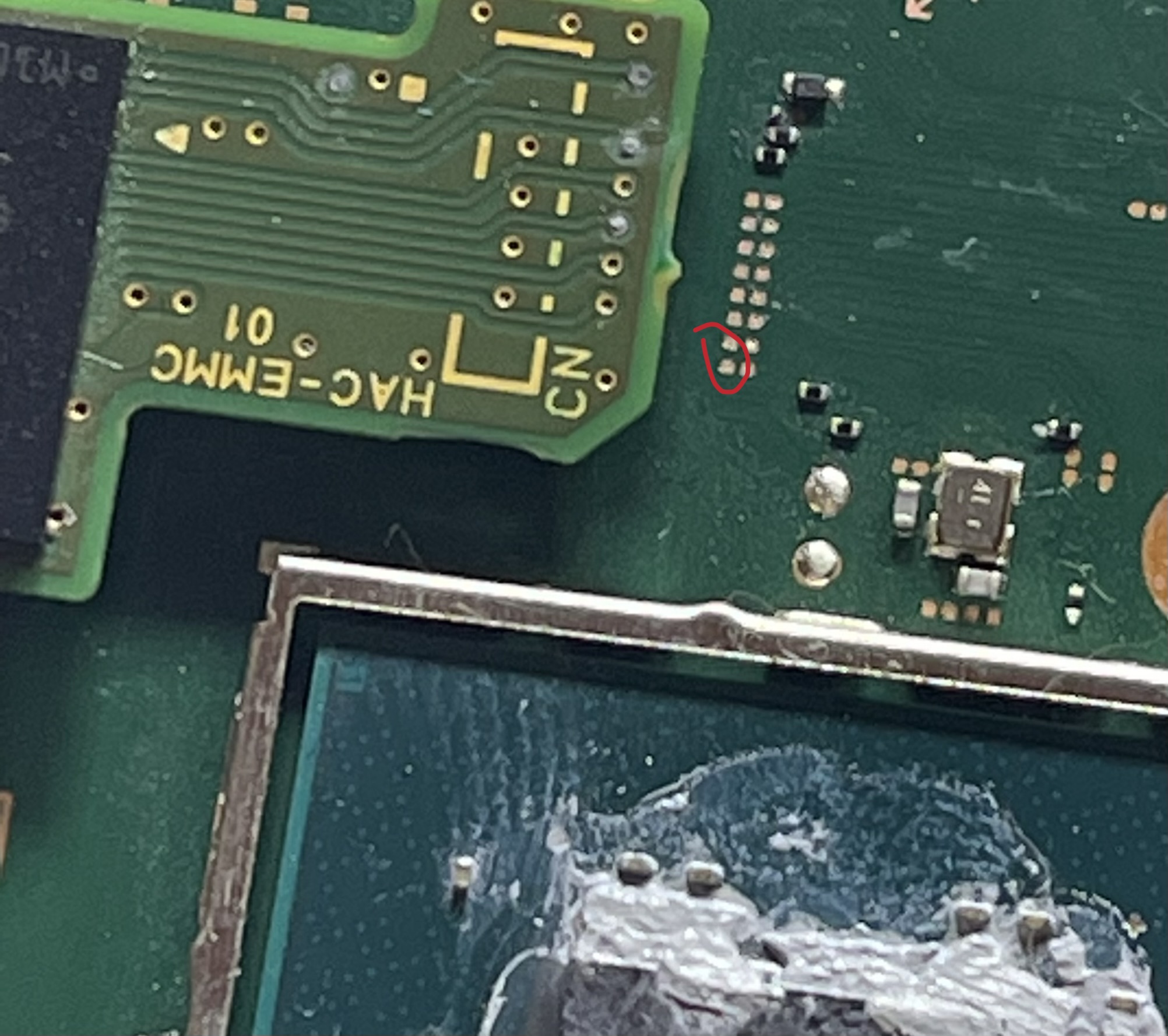
Also this would suggest the EMMC wasn’t a problem (though that doesn’t mean it will work) rather, it’s not causing the shorts your seeing on your board. Can you take a picture of the EMMC module in it’s entirety for me, one of you last pictures I could partially see it but it seems like some potential monkey business was going on here… or, just as likely, could have been a trick of the camera.
As to what actually caused the issue in the first place, no clue but as I touched on earlier one of those shorted rails is for the EMMC - so assuming you soldered everything up correctly then I’m left to assume overvoltage on the rail which might (really big might here) be because of a design flaw with these modchips.
Also just for completeness, take a very close look inside all connectors (LCD connector in particular), as junk or bent pins could potentially put a fault on 1V8PDR, and I guess there is a chance it could pull that other rail down as a result (though I think this is less likely given it’s a soft short but who knows)
I forgot, I also need you to confirm this rail too with your EMMC connected to the board. and as mentioned you should get a reading here (with or without the EMMC connected) – take the measurment at the PI3 cap again) - this is the other rail for your EMMC so it’s quite important this one, I overlooked it earlier.
I’ve forgot what typical is on a good board, maybe something like 18K to 160K (depending)
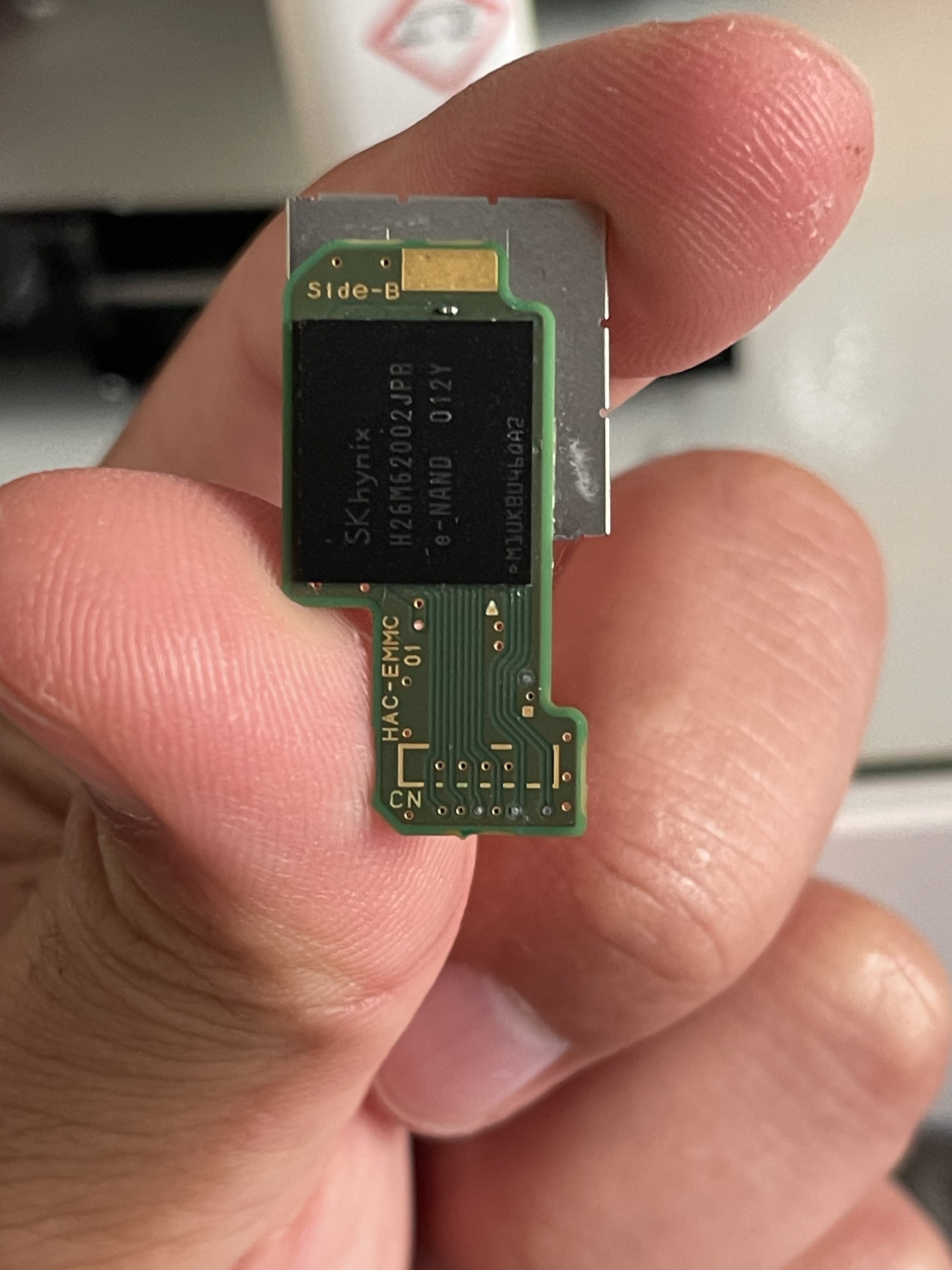
so 24.9 kilohms which is fine. This means you should be fine in attempting to dump the contents on your unpatched switch via Hekate (though make sure you understand about update fuses and the like prior, if this is relevant in your case) - That being said it’s a bit pointless even bothering trying just yet given the mainboard faults. Also your EMMC module looked fine in the picture and the previous image was just trick of the camera so no worries.
checking this topic here
Which is a lite board which uses the same SoC as your board, he’s getting reading in the megaohms on his 1V35PDR. So I think this pretty much confirms the fault in your case.
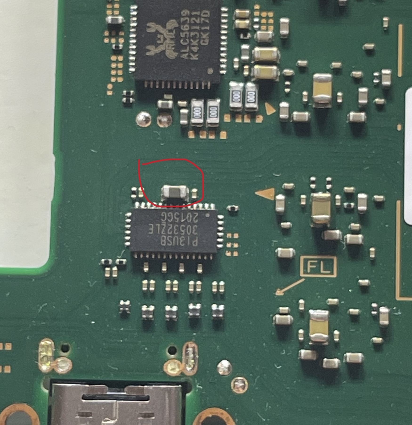
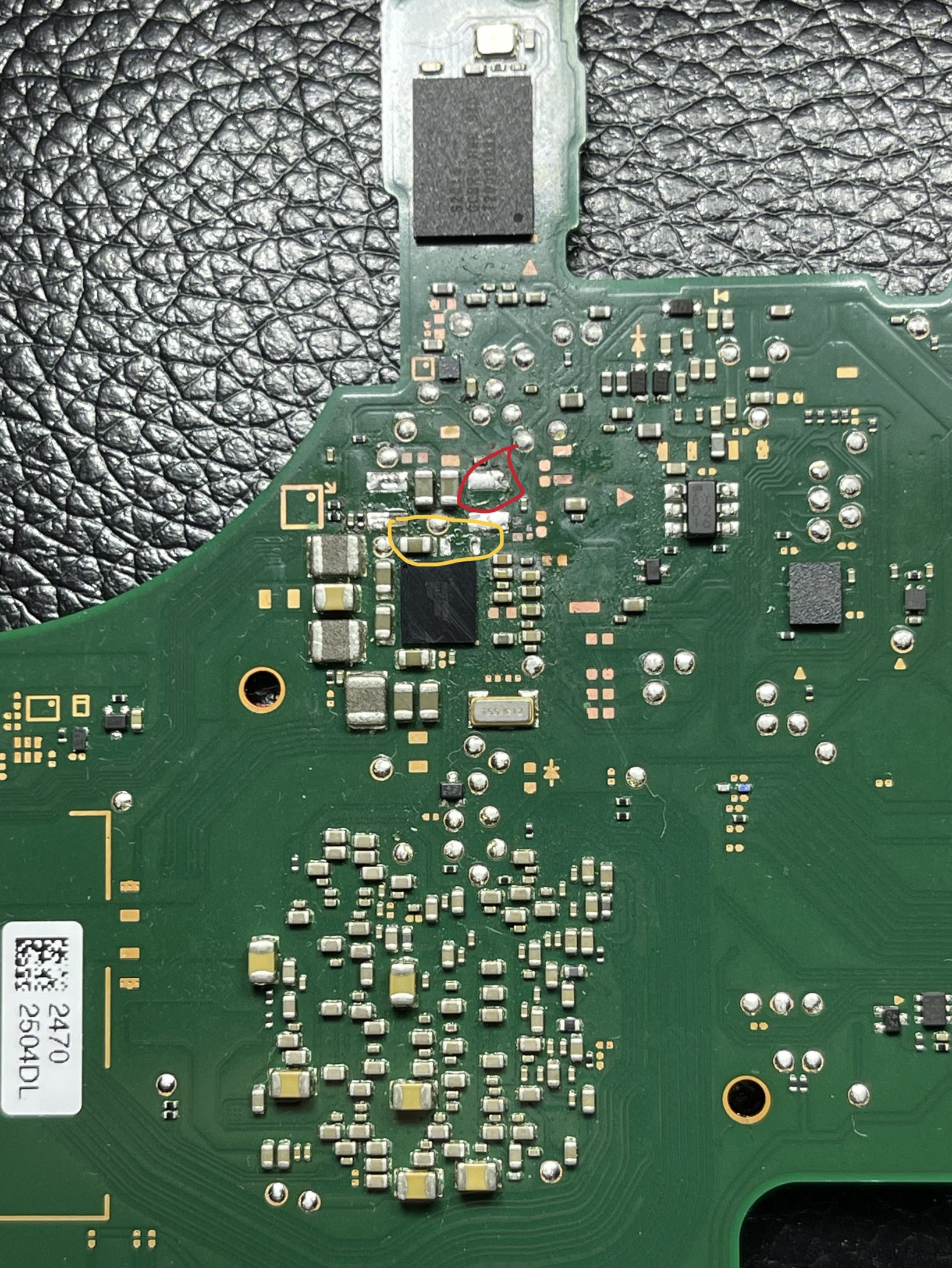
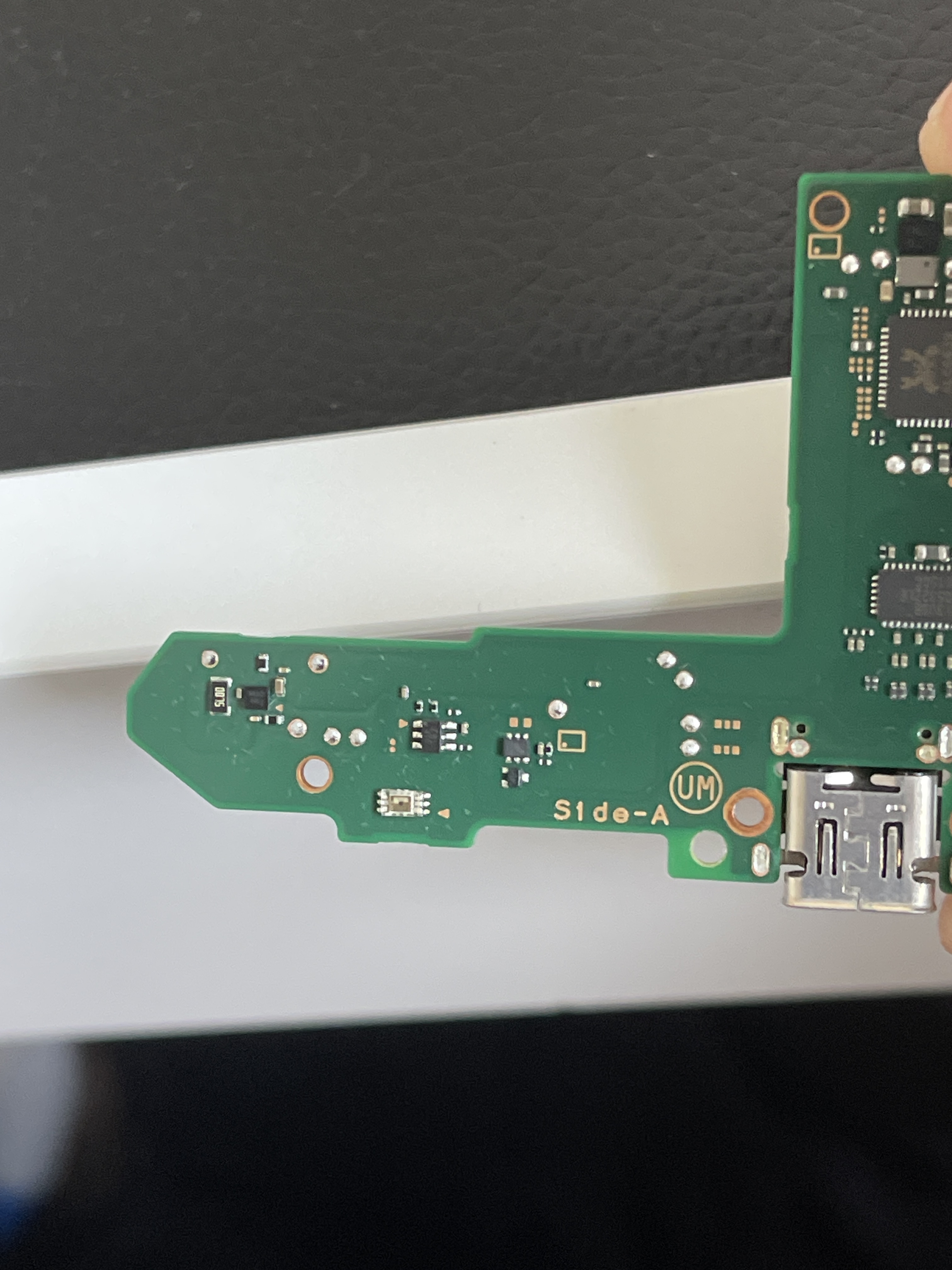
So from your image,
Remove the inductor top left (peach) and the inductor top right (black) and then measure the resistance to ground on all four pads. this will give us a better indication if it’s the PMIC at fault or the SoC, sorry to say I think it’s going to be the SoC but you never know
Also just for completeness, can you take me a picture of the fuel gauge… I don’t see any conceivable way a fault over at the fuel gauge could couse the faults over at the PMIC… but again, worth a look and to cross it off.
I also take it you checked the LCD connector and all others?
Pop those inductors off which I mentioned and take the measurments and we’ll see if there is a chance, though it’s slim, it could be your main PMIC at fault (the max chip in the middle) but we’ll see.
If it’s doesn’t turn out to be the PMIC and it’s the SoC then sorry but no hope I’m afraid
The fuel guage IC (search the forum dude ) I just want to take a look a it
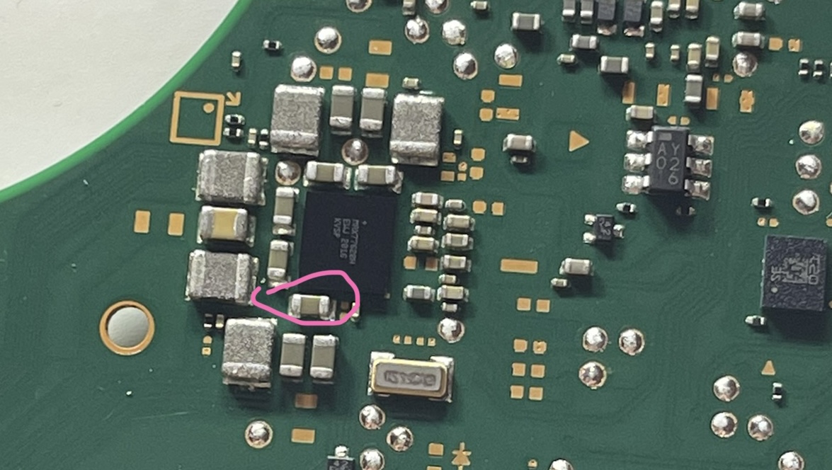
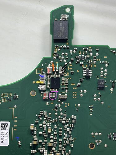
So i managed to get the caps off only the one in red is reading 182.0 ohms the rest no reading on any of the ohms ranges
I also accidentally lost the cap next to the one in yellow would you happen to know what value this is and type if cap so i can get a replacement please to fit back on
The both big components (one marked red) are inductors and not caps. The missing cap below doesn’t matter for getting the board started. It is a bypass cap. Should be replaced (C0603 4.7µF) if you managed to bring this board to life again.
The fuel gauge is on the left down corner on the backside of the battery connector. The really tiny black ic.
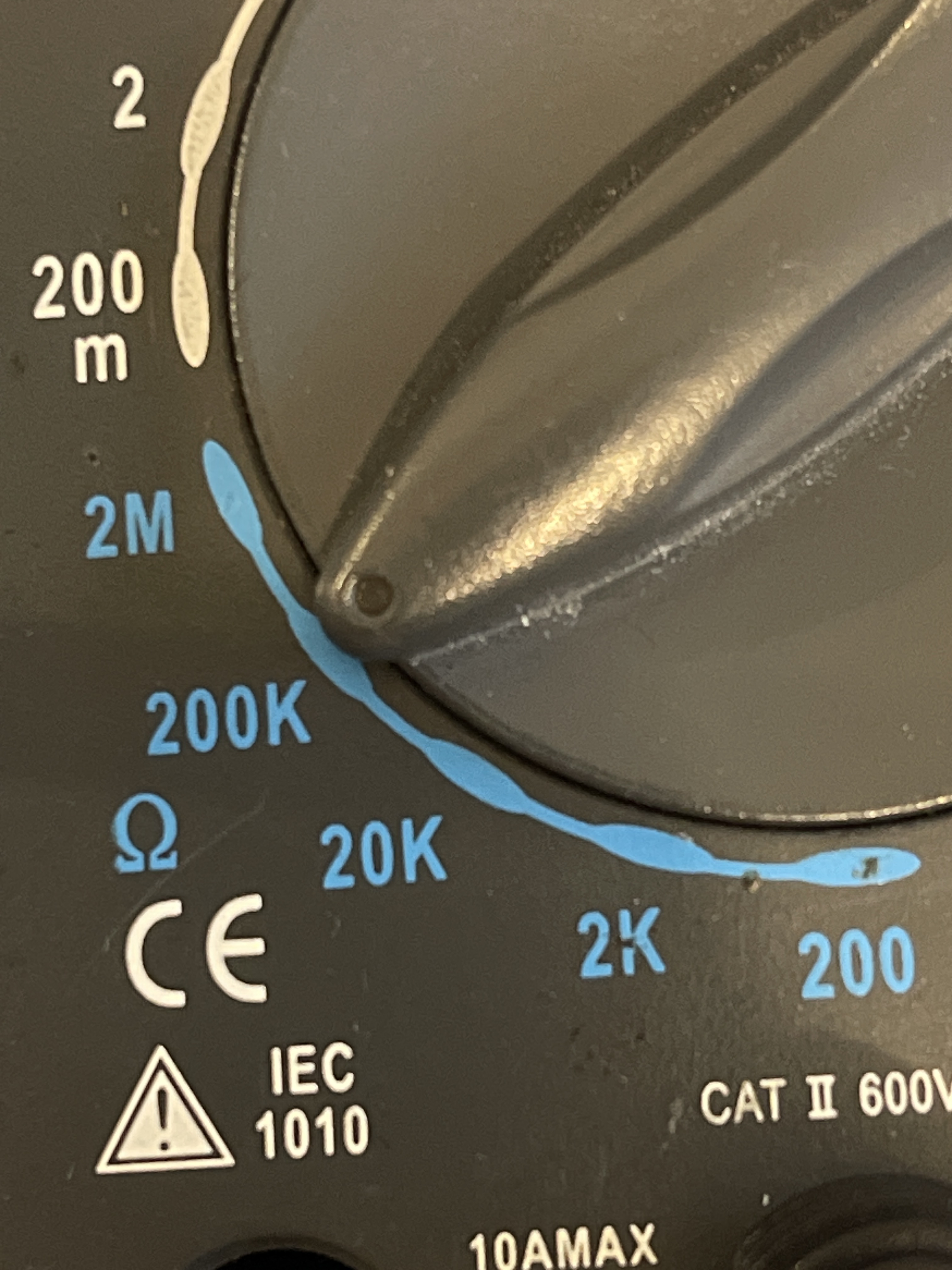
Put your meter in the 2M range and let me know again what your reading on all four of the inductors pads just so I can make sure.
Initial thought is, 1V8PDR is shorted downstream (not the PMIC responsible) which likely points to the SoC being the issue. Interesting 1V35PDR seemingly cleared as a result of removing 1V8PDR inductor. I guess it was happening by way of the PMIC after the fact.