Picofly installed worked first time niw switch fried

So yesterday i installed picofly and soldered it all tothe correct points with enameled copper wires to prevent any shorts from occurring i used a v2 mosfet flex adapter with the latest stable firmware for picofly.

Connectd battery and charger all good i turned it around slightly to see the screen and booted to no sd card screen i turned it back so i can finish off securing the wires then bam pico fly light went out.

Nothing on the screen. I tried to remove battery start again but nothing on switch picofly shows two yellow lights which indicates rst connection which i have checked the over and over it is all good and connected.

No residue flux anywhere.

Everytime i tried to book i couldn’t hear crackling nosies from where the emmc chip is.

I decided to removed everything off and clean up any solders left so no mods are on the device.

Still no life on the switch, however i can hear some kind of coil wine where the emmc chip is when i try to turn it in and when i remove the chip i can still hear it where the capacitors are located.

Can someone please tell me what could the issue be as short circuiting could not have happened as i had put solder mask on all joints before even plugging the power in

Have a read through this thread as your symptoms are pretty much the same

Emphasis on checking your primary rails resistance relative to ground.

Also, can you take a picture of your modchip front and back so I can see specifically which one your using, also just just out of curiosity, can you also take a pic of your EMMC so I can see the part markings.

What your hearing in this area is likely just related to WIFI/BT just below which is normal. so not to worried about this.

Also, if you want, you can scrub that solder mask off and show me all joints which you soldered to (in future don’t use solder mask for jobs like this as it’s not needed :slight_smile: ) just so I can see general board condition.

I am trying to embed the images but i get error stating cannot embed images into post am i doing something wrong

Sorry had to use another website to upload photos and put spaces after https so i can post it

This is my emmc chip where can be see joints

And the bottom of it

https ://ibb.co/18YQKC0

https ://ibb.co/N6HkQHR

I followed the guide exactly
This is the chip

https ://ibb.co/ysxZgd7

Could you help me find where these are

primary rails resistance relative to ground.
Smd resistors were on 29 28 27

Which i had removed when disconnecting everything

Thank you

Can you also show me an image of the SoC so I can inspect soldering work on caps etc now you’ve removed the ribbon.

I’m sure you did, and given it showed you the no SD screen it indicates it was working initially but, if your failing to boot stock standard without the modchip it means as per the thread/topic I linked you to, either EMMC is dead, EMMC partitions are corrupted, or there is a hardware fault somehwere on the board.

Sorry I don’t have the images on my PC but I’ve described the locations on the other thread topic and also posted the locations many times on the forum (as well as pics) so you should be capable of finding them :slight_smile:

Sorry bud this doen’t mean anything to me :man_shrugging: is this a number scheme in the modchip install guide or something (?)

https ://ibb.co/pjkH65f

The pin numbers were the smd locations on the board sorry for not being clear my apologies

I will check aroune your posts for the rail testing

Worht mentioning the board does not work correctly to its not detected by the pc when holding down the the boot button i ordered anew board which should come today i can try again see if that does anything maybe the baord shorted out

If the emmc is dead is there any solution such as getting a replacement emmcs or is the whole switch dead weight now?

no worries.

Good stuff :+1: you can also measure the resistance across the caps which you soldered the ribbon to (which will give details on two of the rails in question) those being your boot CPU rail and your secondary CPU rail (though there is better points to measure these rails as I mention in the other topic/thread)

Of course, and I’m sure it goes without saying but ensure battery is disconnected when measuring resistance in circuit.

In your image of the SoC caps, give this area a scrub with toothbrush and some IPA / and/or gently use a toothpick to removed the thermal compound etc around the caps, sometimes what can happen is the solder can get mixed in with this unbeknownst to you and in turn can drag these rails down as a result.

It’s data is tied to the SoC, there are mthods of using a “donor nand” from another board but I’ve not done it myself as there is limitations such as not being able to use nintendo online services (afaik) - sorry I can’t help you in this regard but there is a video detailing the whole process but we don’t know if that’s your issue yet anyway

What are the resistance values that needs to be read for the caps usually so i can test it against it

I tried to use the emmc chip on my unpatched switch but it does not boot into cfw so this also maybe a sign the emmc being dead unless it wont work kn another switch as its tied to only one cpu

Just let me know the readings your getting

Exactely, because this EMMC is not paired with that Switch SoC, so makes sense.

Nope, but you can dump it’s contents using Hekate on your unpatched switch if you want to verify if it’s alive (if you read the other thread in full then it’s possible you have boot0 corruption which I’ve provided a potential solution to in that thread.though that’s assuming this is actually your problem… I’d sooner verify your primary rails first)

I will get th readings when i get home

Problem is i tried to put thw emmc into my unpatched switch but did not boot into hekate with the sd card i use to boot into it unless i am doing something wrong.

From what i can understand if the emmc ia working it should boot into hekate right and if its faulty it wont am i correct for thinking this

No, provided you’ve got the Hekate files on the SD then you should be able to boot in Hekate with or without the EMMC connected following injection with jig in place.

If on the other hand it’s not booting Hekate as a result of having the EMMC connected then it would imply a short on the EMMC (which can be checked by checking you primary rails on board as mentioned earlier with the eMMC connected to your patient board)

Just for clarity my post above is purely relating to your unpatched unit

Ok so i did my best to test these caps if i missed any please let me know

Values i have measured at whats shown in photo on meter

https ://ibb.co/xhg6T4Z

Red both sides 42.7

Yellow both sides 13.6

Blue both sides 13.6

Green has no reading

https ://ibb.co/bWJnV8L

Red 0.4

Yellow 12.6

Blue 12.6

Grewn 0.4

https ://ibb.co/VqsMdZx

All of these are 0.5

All on emmc board are 0.4

What do you mean by both sides? do you mean in both polarities?

I think what your doing is measuring directly on the caps right?, with one probe on one side and the other probe on the otherside and your then reversing your probes? tbh i’ve got no clue as your second set of readings (same colors) don’t make much sense if that’s what your doing… and it’s like your mixing and matching where your second probe is going.

Your readings around BQ of 0.5 is this ohms or? this includes your SYS rail, I’m not really sure why your SYS rail would be shorted out like this, I mean not impossible (especially if 3V3PDR is shorted out but it wouldn’t usually drag SYS rail this low as a reuslt) but it’s making me somewhat doubt your measurments as a whole.

Anyway bud, do what I told you at the beginning - I’ll go over to the thread for you and copy and paste what I wrote there :slight_smile:

Search the forum regarding 3V3PDR (this is one of the rails for your EMMC) and you’ll find one of it’s many locations, disconnect battery/power and put your black probe on ground and red probe at the other and measure the resistance to ground. Now for your other primary rails do the same thing, but flip the board over and look for the main PMIC (this is a max IC surrounded by inductors, again, search the forum if you unsure of it’s location) and put your red probe on either side of the the inductor (doesn’t matter which side) and measure the resistance to ground and let me know in an image overlay what all your readings were

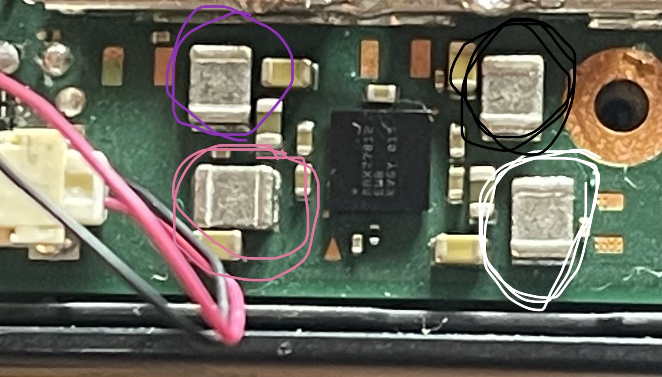
There is only two Max IC’s on the Switch board which are surrounded by inductors so I have faith in you that you can find them :smiley: but for clarification, there is one just below the SoC (which I can see in your image) you can take readings as I mention in my quote above IE: black probe on ground - put it on a screw hole pad or at the USB ground through hole pad/s and red probe on either side of the x4 surrounding inductors (doesn’t matter which side) this will give me the details required for your secondary CPU rail as well as your GPU rail.

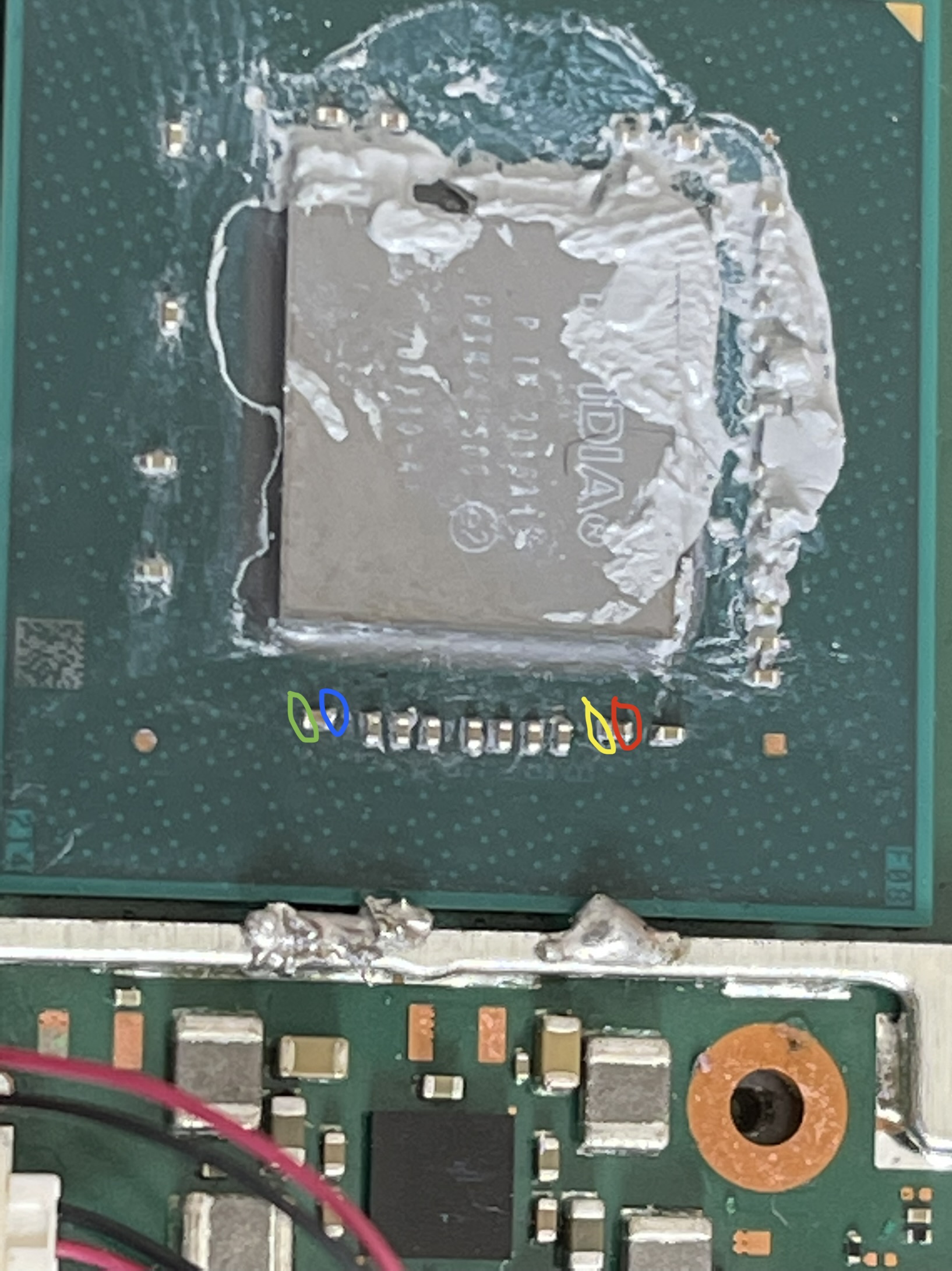
Next flip the board over, you’ll see another Max IC surrounded by inductors (this is the PMIC) do the same thing here.

3V3PDR, you can just measure this at at the 3.3V location on the EMMC if that’s easier for you, again black probe on ground and red on the TP.

For your SYS rail (we’ll check again) again put your black probe on ground (screw hole pad/usb through hole) and red probe on either side of the 2R2 inductor (doesn’t matter which side) next to the BQ IC (I don’t see the diode so I’d expect somewhere in the region of 10k into the megaohms - depending, on an otherwise good board)

Now, because your meter is not auto ranging you’ll have to understand how and when to change the dial and how to interpret what is being shown on the screen (sorry I can’t do this for you as they are all different) it does me no good if you tell me “0.4” if i don’t no if that’s Ohms or Kiloohms or Megaohms :slight_smile: you also have to understand when it’s gone over limit/over scale or underscale as some will simply display 0 and some a 1, some OL some 01 etc etc (this is why I cannot stand horrible cheap manual ranging meters :slight_smile: ) . A tip, stick it in it’s highest mode (in your case 2M range) and work your way down the ranges to get the most resolution without going under or over scale.

Also, did you manage to boot into Hekate on your unpatched unit?

If none of that makes sense just lemme know and I’ll try clarify for you :+1:

So what i done is i put black probe on ground usb and then the other measured each cap when i say both side i meant i measured each side of the cap while on ground and put the colours of each side that I measured and listed the readings on the image which it has the whole caps in circles both sides of the caps read the same

I will do as you said and measure and work out rhe meter readings so it makes it easier

I have not yet tried the unpatched again am.a.bit worried if the emmc is faulty if it would damage the unpatched switch to

I was thinking to get something like this to try read the emmc and back it up if that’s possible what do you think

https ://uk.rs-online.com/web/p/rock-sbc-add-ons/2565000?cm_mmc=UK-PLA-DS3A--google--CSS_PLA_UK_EN_Raspberry_Pi_%26_Arduino_%26_ROCK_%26_Development_Tools_Mob_Whoop--ROCK+SBC+Add-ons_Whoop+(2)--2565000&matchtype=&pla-299950726736&gclid=EAIaIQobChMInsLpgPuCgQMVxux3Ch19AwMZEAQYASABEgJzW_D_BwE&gclsrc=aw.ds

Yeah even then your readings don’t make sense. These are bypass caps (one side is directly connected to ground) - for example you were reading “Yellow both sides 13.6” & “Yellow 12.6” - see what i mean? one side should measure virtually zero. Maybe your multimeter leads/probes (or meter contacts) are dodgy? Or you were in the wrong range, or you probed the cap directly with both probes or (?)

Fair point, but as mentioned you can boot the unpatched Switch into Hekate without any EMMC module connected (incase you want to check it still works and if we verify your patient EMMC is actually good/safe based on rail measurments)

Provided you leave the patient EMMC connected to the board while taking the measurments we talked about, we are going to be subsequently measuring the two primary rails for the EMMC module and in so doing determining if it’s good or bad, if it’s good (or maybe i should rather say safe), you will be able to use your unpatched board to safely attempt to dump it’s contents (though this doesn’t gurantee you’ll actually be able to but it does mostly confirm it’s safe to attempt on your other board) if on the other hand the rails in question are shorted to ground, and if after disconnecting the EMMC those shorts on the mainboard disappear then it indicates a fault on the EMMC module itself and it won’t matter if you get that reader from RS as it won’t help.

In regards to the Reader, provided the pinout on the connector matches the pinout on Switch and/or your comfortable point to point wiring the lines up to the board if it doesn’t, then I don’t see why not. The only thing that would need confirmed is that you can access the two hidden partitions (which many readers cannot do) those being boot0 and boot1.

I think Nintendo secretly love the picofly.
The growing amounts on failed install picofly attemps from users which are not used to microsoldering and ruining their Switches are increasing the sells number for new Switches… :stuck_out_tongue_closed_eyes:

2 Likes

white both sides 42.7

Purple both sides 13.6

pink both sides 13.6

Black has no reading

Red 0.4

Yellow 12.6

Blue 12.6

Green 0.4

So the above readings are for two different parts i have changed the colours to make it easier to read

When i measured them i used ohms 200 lowest setting so the reading should i believe be just ohms and the probs are good they are new and i always made sure not to touch anything else but the side of the caps while touching ground on usb

Do you think if i measured the emmc chip on the unpatched switch without battery plugged in this will show us if its bad or not

Do you think if i booted into hekate with my normal unpatched emmc and then remove it and put in the one in question would it work and be detected

Or is it a bad idea

Haha I think you might be right :rofl:

Question for me though is, is it just because the cost is significantly lower that it’s opened the floodgates and a higher number of inexperienced users are attempting or is it because of the modchip hardware or software… I mean we saw plenty of examples of bad original SX installs (and 1:1 clone installs) back in the day but the number of deaths in the manner we’ve seen were significantly less and most related to shorted rails at the caps on SoC, ribbon or a failure of the SX modchip itself - typically knocking said caps off and/or removing the modchip resolved the problem - I mean I’m looking at the OP’s soldering joints and nothing looks bad to me, and it did work initially so I’m left looking at the EMMC hardware death or data corruption - which has me thinking on the lack of shift registers on a lot of these newer mod chips… and then thinking is it because the percentage of people affected by this is low but the number of people using them is high :thinking: … I dunno :upside_down_face: hoopefully this topic can provide some clarity.

No, the readings your taking at the indcutors correlate with one of rails on the SoC cap (so don’t worry about that) and afaict your readings here are in the realm of normal for the two rails I was interested in.on a Mariko board.

Next, you need to flip the board over and do the same on the other Max IC I mentioned and after - 3V3PDR, and SYS :+1:

As I meantioned earlier, the resistance to ground measurments I’m asking you to take will confirm whether your EMMC is physically bad/safe or not. So no, keep it plugged into you patient board until aftyer I’ve confirmed your other rail readings :+1:

It’s a bad Idea, I do not like hotplugging EMMC’s at all but I especially don’t like doing it with potentially bad IC’s … Wait until after I confirm your measurments, if it’s safe I’ll let you know and you can attempt to dump it’s contents on your unpatched board.