I did not have voltage on pin 6 from m92t36 and it was suggested to replace the ENXX chip. I ordered some but I must have rubbed the green mask off when I was cleaning the pads off and now I am not certain if it can still be used. I replaced the chip once already but it sat crooked and I suspect the pins are bridging underneath and causing the issue. Still no voltage on pin 6. I have a comparison image from another fresh board for comparison.
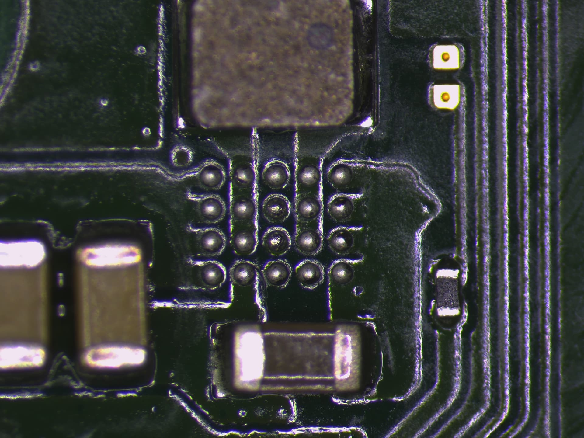
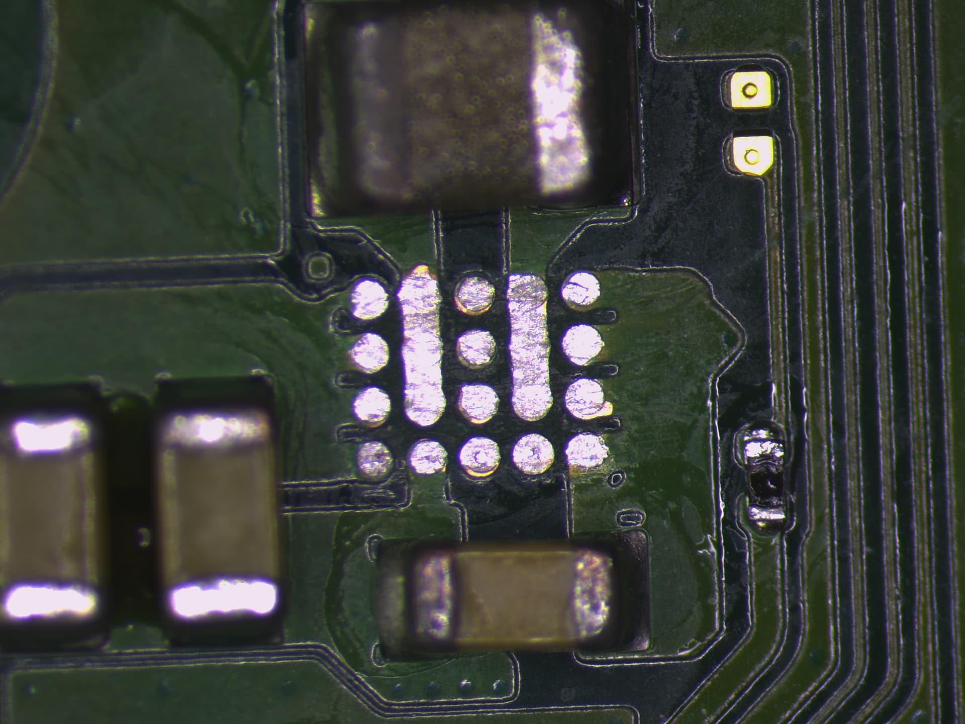
Those row of 3 pads are connected, same with the other row of 3
Seems to me your iron wasn’t hot enough and you’ve just taken off the mask, think one thing that’s hard to perceive if your just starting out or watching videos for examples is the goal is to get the board and wick up to a high enough temp to allow the wick to suck the solder up, the wick should be effectively floating over the board, if they’re not up to temp and/or your applying too much pressure the the wick won’t suck up the solder and the wick will act as a really great abrasive (think kitchen steel scouring pad)
Some soldering irons/stations/tips are simply don’t have the heat capacity to wick higher mass areas on some boards, if your iron is in this category then have your hot air help out while your doing the wicking process with your iron, hold the hot air in the vicinity at about 150C low air which will really help out 
Trouble when you start losing solder mask like this is that those overexposed pads will now cause the solder balls to be sucked down and make the solder spread out, this can cause the chip to not align properly during reflow or cause it to sit funny - kind of almost looking squshed as it can become “sucked” down, this has the potential to cause the other balls to follow suit and potentially bridge together… that being said, sometimes you can get away with it… but I’m a bit pedantic and would wick those pads properly, clean, and apply a very thin layer of UV mask over the exposed areas then re-reveal the pads with my blade
The inductor above and the cap below, the end-caps look a bit blackened, not sure if this is as a result of liquid or corrosion or maybe an over aggressive flux, but I’d touch them up so the joints look shiny too
Thank you. I knew they were connected but I suspected the same thing, that it was pulling the solder balls. I have some mask on order and will give that a go. I’ll tackle or maybe even replace those other 2 components also while I’m working on it.
I’ll update once everything arrives next week.
OK, So my solder mask arrived and I was able to seperate the individual pads. I then attached a brand new ENXX chip and it looks perfectly lined up and from the angles I can see the solder balls look great. Unfortunately I still have no voltage on pin 6 from my m92 chip. I have normal voltage on pins 5,9,21,22, and 23. The BQ chip has voltage on pins 1 and 24 (the last pin, i forget the number). My fuse is not blown. I have 5 V on the 2 voltage pins from the USB (4 from the left and the right). At this point I am not sure what is next to check. Obviously voltage is being stopped somewhere, but how do I determine where? Is there a way to see if I have power up to the ENXX chip but not out? Any guidance would be appreciated, this one has me stumped so far.
Note: I do not see any shorting caps around the m92 or the BQ, but I have not exchanged these chips, still factory.
The EN IC is a RP602Z330C
This board pinout i created is a bit dated and this is a different rev Switch board but you should get the idea
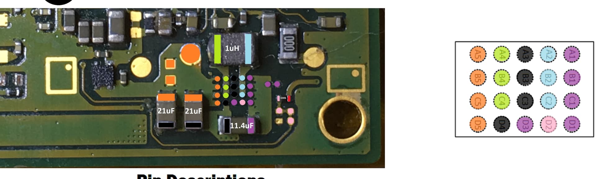
D2 (pink) is the enable line, If the resistor nearby is 100K on your board then it will be the same, you’d wanna buzz out D2 (pink) to one side of that resistor, if you’ve got it, then you’d prompt the console to boot and see if this enable line is a logical high (1V8) which would mean the chip is being told to turn on the output
Might also be worth measuring the resistance to ground on the output (orange) just incase something is dragging this rail down.
Ive heard you talk about “buzzing out” a line before. I am not familiar with that term, could you elaborate?
In order to test that resistor, can I test it in line or do I need to remove it from the board?
In order to test the 1v8 on boot, do I test the voltage on the pink side of the resistor you have highlighted or on the nearby pad?
I should also mention this is a switch lite board. The layout will be a little different but will they both use the same components?
I will be checking these measurements when I get home. Thank you.
Yeah, I just mean checking for continuity (buzz) between two points in question
You don’t even really have to do that step, if the resistor is approx 100K (and yeah you can check this in circuit) then it’s almost guaranteed it’s connected to the enable ball/pad of the IC, then you’d just prompt the console to boot and ensure your getting 1.8V on both sides, if one side is low then it’s likely the side of the resistor which connected to the D2 ball/pad and as a result tells you that the IC is not even being told to turn on the output, hope that makes sense ![]()
In regards to this area, the IC is the same, and most (if not all) surrounding components will be identical, but the layout is certainly different
OK, so I’ve buzzed out the line and I have continuity from D2 to the resistor and the pads. Prompting the console to boot does not produce voltage with the chip installed or without the chip installed.
The resistance measures 98.2K Ohm. I am assuming that is close enough to 100K to be considered correct.
So something somewhere is preventing that line from receiving voltage… Any idea where I should start tracing this back?
As far as I can tell, the 1.8v enable comes directly from the main PMIC on the switch lite.
Following prompting the console to boot, do you measure 1.8V on the other side of that resistor?
With battery/power disconnected what is the resistance to ground at the point in orange from the previous image?
I could be wrong, but if memory serves I think the 100K resistor is serving as a weak pull up to 1V8PDR and the enable line goes off directly to the SoC… though I could well be wrong as it’s been a while since I checked
It definitely leads to the SoC on the normal switch, but it looks like on the Lite its heading to the PMIC (at least going from the board layers).
I have no voltage on either side of the resistor before or after attempting to boot. With or without the chip, to be clear.
In regards to the resistance to ground. Each of the 4 orange points under the chip (chip removed obviously) has a resistance reading that starts anywhere from 2 to 17 million ohm and quickly starts to drop and will continuously drop. Both caps on the orange side follow a similar pattern. The two square copper points and the round copper point are similar, but if I take the same reading multiple times, sometimes it will start at 0 and begin to climb into the hundreds of thousands. Then if I lift the lead and try again it will start in the millions and begin to drop. It mostly counties this cycle. This is with black lead on ground red on orange points.
This is the first troubleshooting I’ve done using resistance, so I’m not sure if this is an expected pattern/result, if something is wrong, or if I am doing it wrong.
So your missing your 1V8PDR (one side of that resistor) which likely indicates (assuming your relying on the USB to prompt it to boot) that you have USB or M92 related issues, without your 1V8PDR you won’t in turn get your 1V8 enable, so I would try using the power button flex and using the tact switch to prompt the console to boot with battery connected, or shorting the pwr pin at the flex connector to ground with some tweezers and then seeing if your 1V8PDR shows up at one side of the resistor (and maybe even your 1V8 enable signal the other side)
I expect your inconsistent resistance readings are as a result of your meter, not to worried if it’s leaning more towards an open
I have been using the power button flex to prompt boot for each of my tests with known good battery and USB both connected.
I can certainly replace the m92 if you think it may be the source of the problem. Is there a way I could troubleshoot the USB? I assume though, if nothing is happening with the battery connected when trying to boot, that the USB would not be the culprit (Physical inspection looks good also).
Man this would be so much easier if Nintendo would stop being jackasses and release a diagram where we could trace these lines.
Hmm do you get voltage at your SYS rail? you can find that at the large 2R2 coil near the BQ IC
If yes, then I would check the other rails at the inductors surrounding the main max PMIC following [attempted] prompting to boot
I think it’s unlikely you have a bad USB and power/vol flex cable at the same time so I’m not thinking this is a USB issue anymore, though I suppose it’s always a possiblity, to verfy it you would use a USBC breakout and verify continuity to all relevant board destinations using one of the many diagrams here. You could also do the same thing with the power/vol flex and put your meter in continuity and press the tact switches on the flex and place one probe on ground and work your way across the connector pins and ensure it beeps (one of the pins is ground)
Don’t know if you mentioned already, but I’d also check the fuse just above the USB port and ensure it’s not open
Yes, I’ve checked the fuse and it is good.
I have not checked the sys rail, this is where I start to get a I’ve my head at the moment. Working to learn more about it. What exactly would I be checking for? Am I looking for voltage? Does it matter which side of the coil? Which inductors are you referring to (around the 77620?) And how do I check that rail?
Approx 4V
nope
All of them, multiple rails being produced here, I’m just curious if any are as we know your missing one of them allready (1V8PDR) so attempt to prompt the console to boot and see if there is any voltages present on the surrounding inductors ![]()
That being said, wait until you’ve verified your SYS rail first before checking those other rails, if your missing SYS you won’t get any being produced by the main PMIC
Understood. When I am promoting to boot. Am I looking for a signal only during the oromot or do I prompt to boot then I’m good to test for a while?
yep with battery connected and follwing prompt, rails in question will sustain under normal circumstances:![]()
Well, I do not have voltage at the 2R2 coil or anything around the PMIC (as you already mentioned I would not in this case).
I do have a 4v line to 1 of the caps between the bq chip and the 2r2 coil. and also on a cap above the m92 chip. Poking around random points around the bq and m92 I have 1.3v and 1.8v rails active but still nothing on point 6 on the m92 or anything else which we have already discussed.