Second try on BSOD reflow/reball!

Hey everyone, it’s me again!

I ended up selling my other switch on eBay as is. Considering the CPU on that was done for.

I ended up getting a better rework station (I hope? YIHUA 995D) and got my hands on another BSOD switch.

This time, I tried a reflow on the eMMC chip and the SoC, I used less heat, warmed up the back side from 150 - 200 and then 400 - 450 to the front. I tried at 420 but it wouldn’t budge until I tried 450. I was able to nudge it on all sides/corners.

Upon putting everything back together (sticky flux everywhere even though I used original amtech no clean), the BSOD is still there.

I’m happy that I didn’t fry the SoC like last time, the other one just didn’t come back on after.

I read just about everything I could on here when it comes to BSOD, it seems as though most were able to solve theirs with reflows/reballs.

I don’t mind attempting a reball, I just want to make sure I’m reballing the actual problem. Any advice how to narrow down what could be the issue?

Remember, I already tried the eMMC and SoC with the same results.

Are there fuses, or diodes, resistors I need to check that could cause BSOD?

Thank you in advance!

This is going to be a bit long but it’s worth covering as beginners tend to make the same mistakes when working on a board.

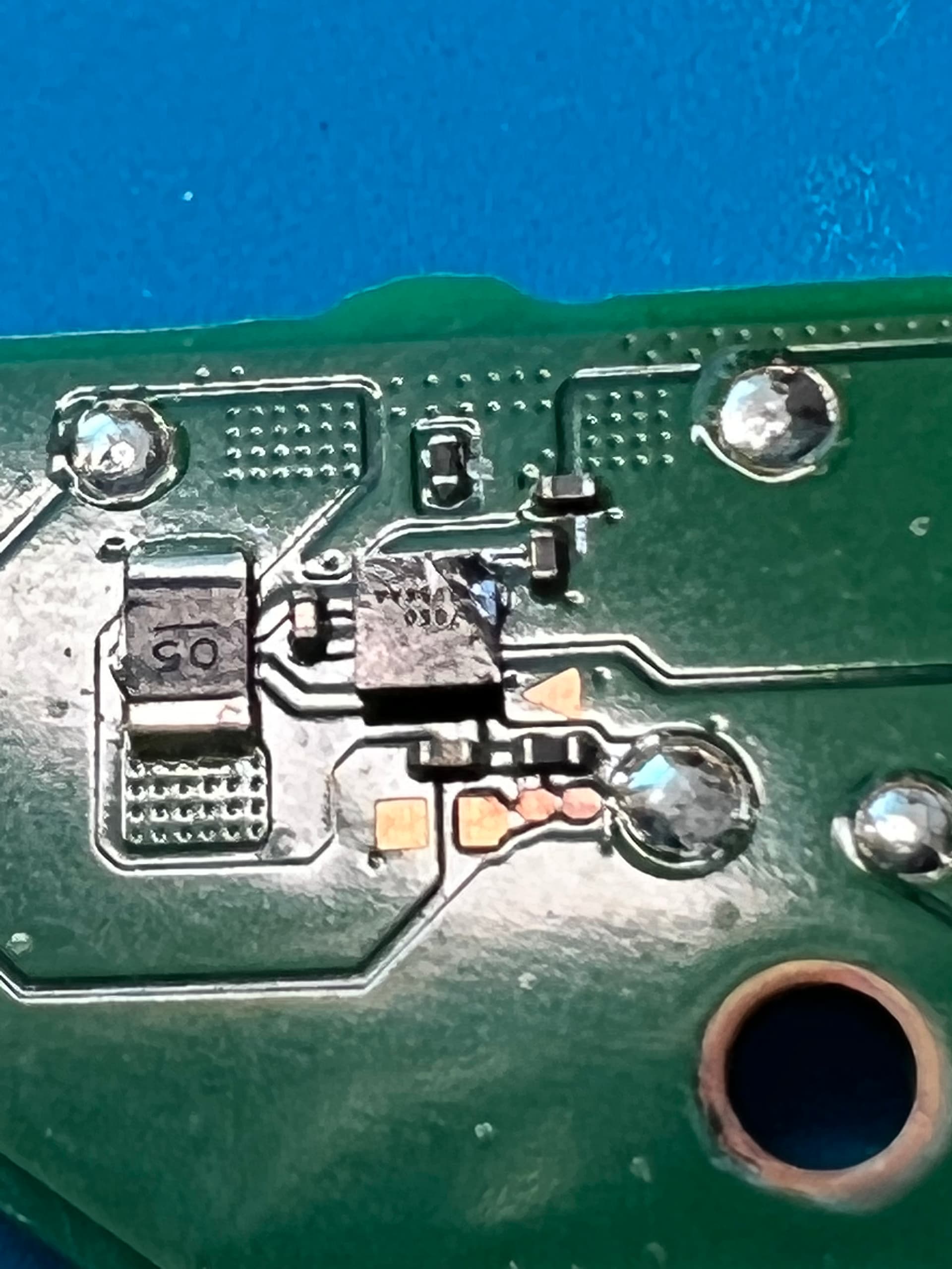
A few important points to remember - and I’l start with reflowing - is, the only time a reflow is going to resolve a problem is if one, the chip/components which are to be reflown have corrosion / liquid below them and by reflowing with flux your effectively “washing” it away (though more likely just lessening it) - for example, there is an IC which has a primary input rail at 5V and several ground pads, corrosion has caused a short or a partial short from the 5V line (or pads in this case) to the ground pads, thus preventing the chip from powering up due to the 5V line being pulled low.

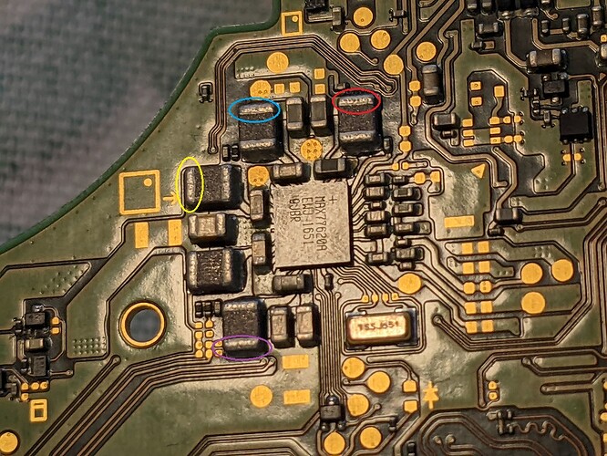
Second case for reflow would be joint failure which could be for one of two reasons - first being impact damage, in these instances we look out for clues of impact, in the case of Switch (and other handheld devices) you’d look at the outer & inner assembly for signs of impact damage, you’d also look at the board and see if there is any component damage, for example, bare die ICs (which are glass like) tend to fracture or chip, in extreme cases capacitors will shear clean off the board leaving very behind noticeable bare pads (often with the caps endcaps still attached). The second cause for joint failure would be board releated stress (and again this is more common on handheld devices) so you would again look at the main assembly and frame and check if there is any warp or twist, you’d also once again remove and take a close look at the board for any warp or twist too.

Now, in the first case of liquid or corrosion, you’ll have to use your better judgment here, if it’s extremely minimal corrosion you can sometimes make the determination that a “flux & boil” is enough to clean it out, sometimes that’s not enough and flux and reflow is the way but if the corrosion is too extreme or there is a suspicion of larger damage (below an IC for example) let’s say corrosion which has eaten through traces or corrosion which a reflow or flux and boil will not clean up enough then you might make the determination to remove the IC entirely to inspect (and reball/replace the IC if applicable)

So to summarise, you’d only ever reflow something if there was clear signs of corrosion/liquid, and you’d only attempt the reflow if the corrosion/liquid damage was minimal or more or less just superficial. In the case of suspected joint issues, you’d only ever reflow if there was clear signs of impact damage elsewhere, the gotcha here is, if the joint damage occured not as a result of drop/impact reasons but instead as a result of board related stress (maybe due to a bent frame, twisted etc) then it’s pretty unlikely a simple reflow will resolve, the reason being that what is most common in these cases to cause pad, VIA and trace level damage (usually below larger ICs) in these cases and when the reflow seemingly does resolve the issue, you’ll typically find the reflow only temporarily resolved the issue (for example trace damge on the mainboard below the SoC, heat has caused expansion/contraction and thus “moved” something, maybe reconnecting a line) This is why I say in instances where the board has clearly been stressed (bananna shaped boards for example) don’t torture the SoC with a reflow but instead either transfer the SoC and EMMC to another known good mainboard or go straight for SoC removal and inspect the PCB for VIA/trace issues (but again I wouldn’t suggest a beginner even goes down this road without extensive practice)

It’s also worth noting, even if there is clear signs impact elsewhere and the other symptoms align and a reflow is conducted, this doesn’t gurantee success, you still have to hope whatever ball which has potentially disconnected hasn’t fully sheared off and isn’t just floating around below, as if it is, no amount of reflowing will help.

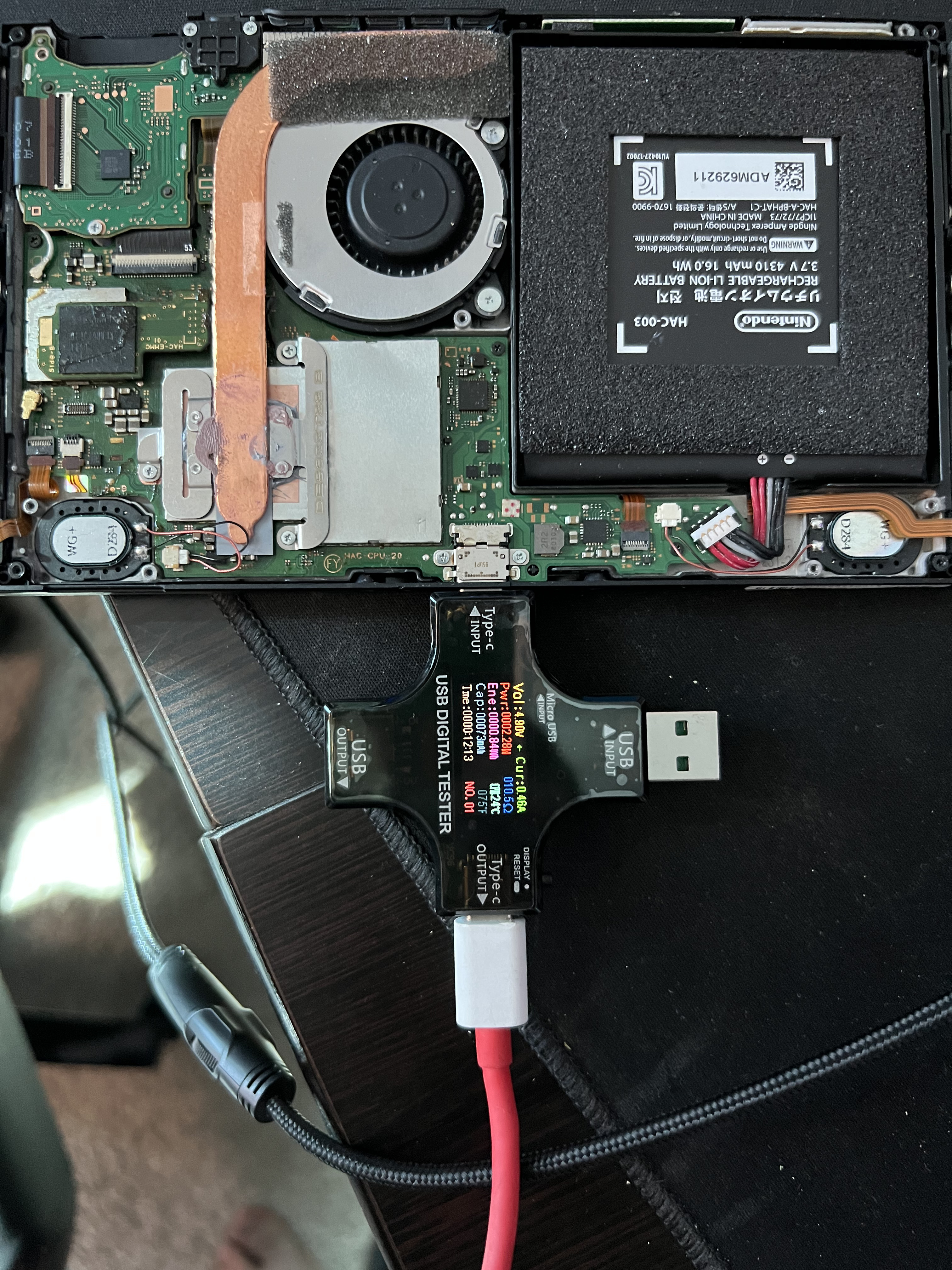
Now in your case I see you went for the EMMC, I can tell you from my experience and reparing over 100 Switch consoles I thnk I’ve had maybe two cases where a BSOD was caused by an EMMC hardware related issue and maybe once where the BSOD was caused by EMMC data corruption. So I’m not saying that’s not your issue but rather just letting you know how likely/unlikely this is.

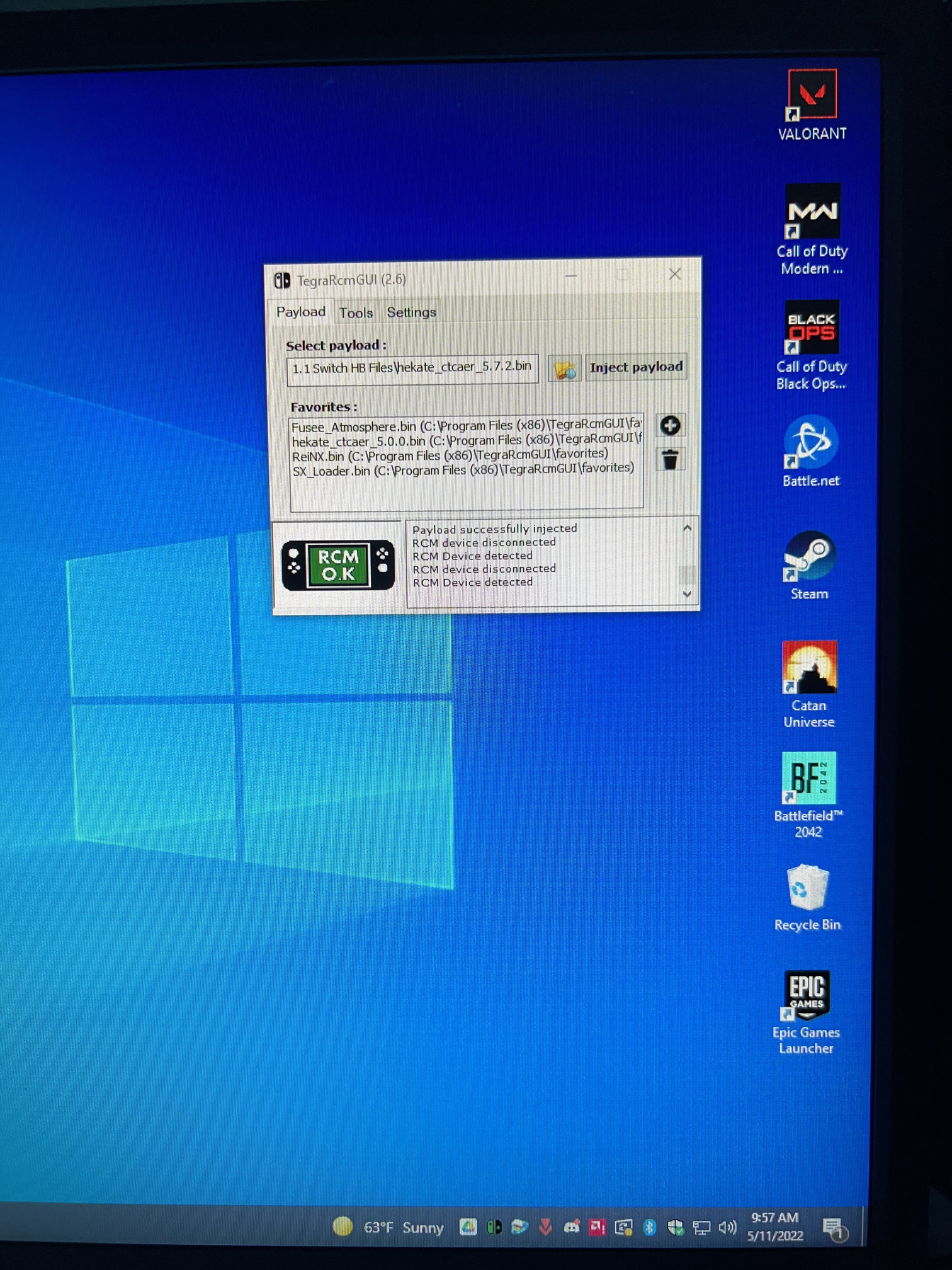
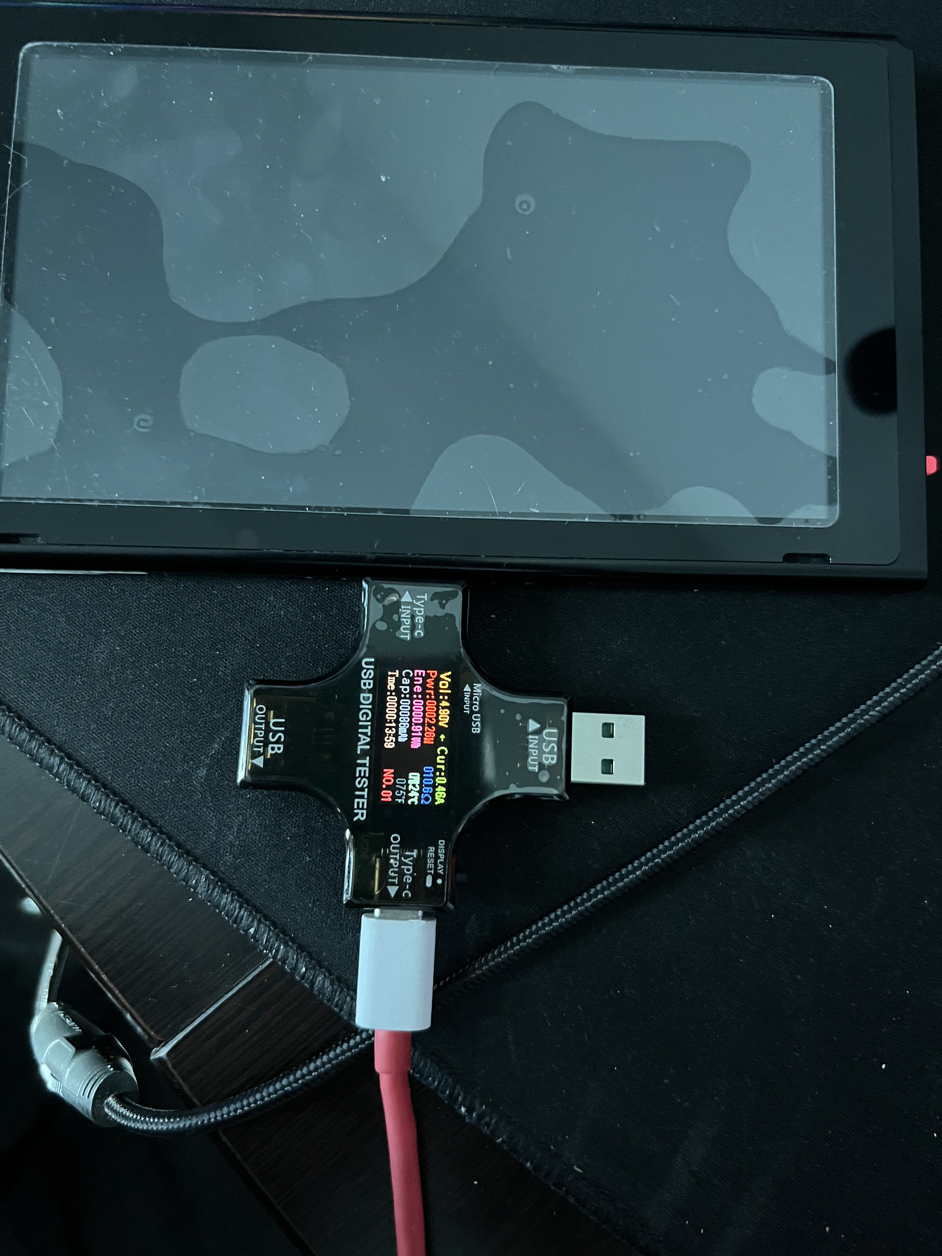
Next time, start with a less invasive method, check to see if the console is unpatched, if it is then (with a jig) boot up Hekate and verify if the EMMC can be read, if it can it’s highly unlikely to be an EMMC fault causing the BSOD. If it’s patched, then plug it in to your computer, if it’s detected as being in RCM mode it might be pointing to an EMMC ralted issue and you can move onto the next step. if it’s patched and it doesn’t show up in RCM state on PC then it’s less likely to be EMMC related (though this largely depends on other potential board faults)

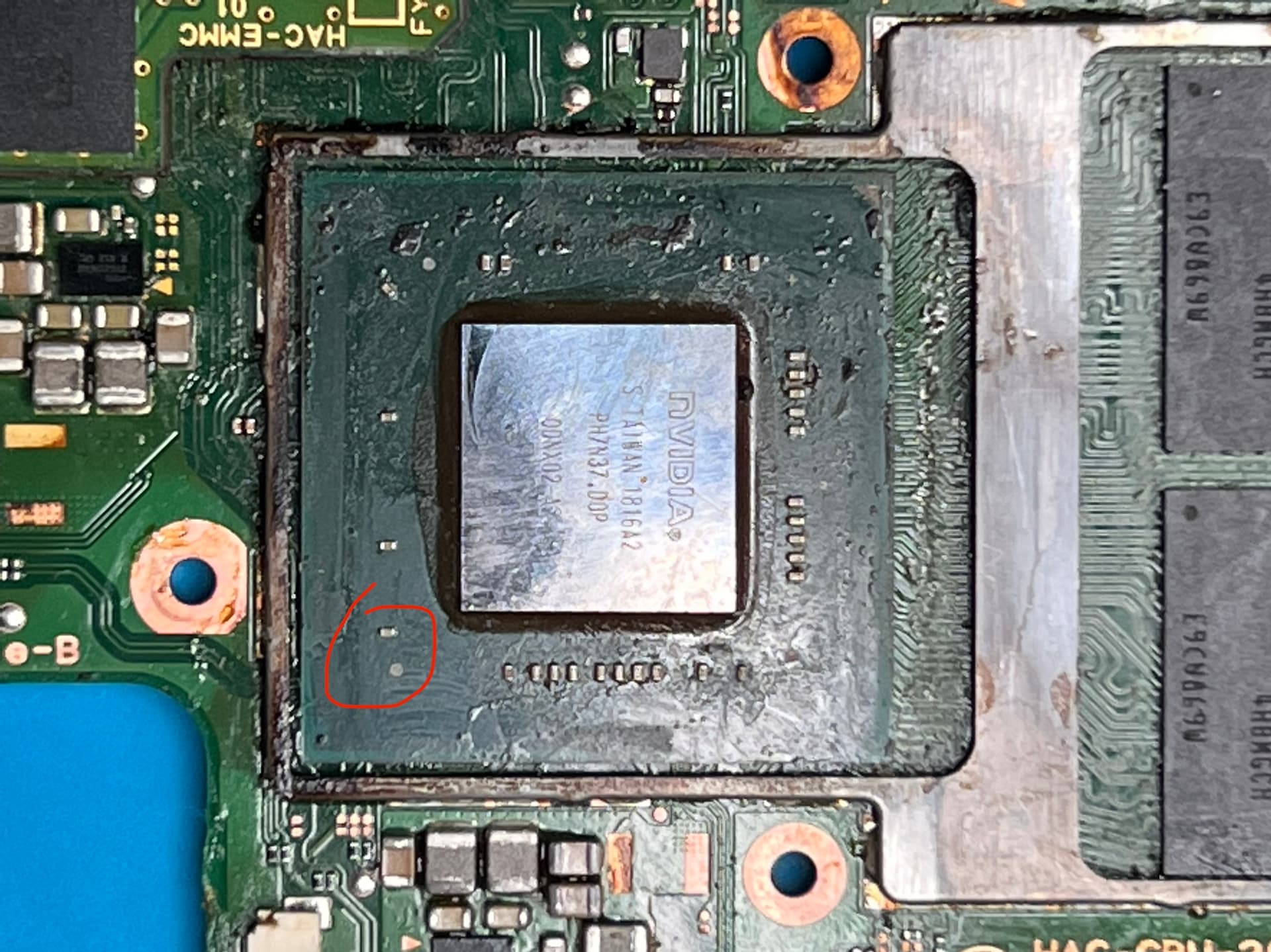
Working on the SoC is the absolute last resort, as I mentioned in the last topic of yours, BSOD is not just caused by the SoC, there is about 5 common reasons for it with the most likely being the fuel gauge, then ram then SoC and sometimes PMIC and sometimes EMMC related issues. The SoC is incredibly sensitive to heat, if your hot air gun is not up to the task all you will achieve is cooking it which tends to kill the low voltage rails in particular the CPU rails, this is because the die (the glass like section in the middle of the wafer) fractures internally in the process of abuse, a hard rigid material on a “soft” flexible wafer both materials expanding and contracting at different rates during heat up.

Good question, these are all things you should know the answer to before going down a reflow (and in particular the SoC reflow) route :smiley: answers which I (and others) have covered a bunch on this very forum :stuck_out_tongue: by sifting through hundreds of topics you will learn other things in the process which will ultimately help you in the long run.

Anyway hope that helps.

3 Likes

I really appreciate the breakdown and explanation. It was definitely helpful and informative.

From sifting through the forums, I’ve also come to the understanding that reflow only works in certain scenarios.

I was hoping to get lucky I guess, but I totally understand the steps and procedures to diagnose a problem and how important it is just in general when trying to repair electronics.

This is definitely something I will need to learn and practice in order to get a hang of.

I’ve read about this fuel gauge, if I remember correctly, there’s a way to confirm this through checking to see if the switch is patched or not, which in this case it’s not.

I just plugged it into the PC, and with the jig in place, I was able to successfully enter RCM mode. (I obviously couldn’t inject anything because it’s patched)

I was also able to get some readings…


Is it safe to assume I didn’t fry the SoC? :slight_smile: (If so, huge sigh of relief because i’m learning immensely.)

It seems I need to find what I can on this fuel gauge. I did find quite a lot, but the information was as mentioned, all over. I’ll try to do a search, if you or anyone else here doesn’t mind narrowing down a specific thread I should read over, please feel free. I’m at the excited stage, with hopes I might actually be able to fix this switch.

Also, any comments on the rework station I bought? Know anything about the quality or reliability?

Visual inspection first (and a visual inspection first in general) and checking the physical health of the fuel gauge IC, this is another “glass” like package, which makes it fragile, while they can sometimes still operate with small nicks and cracks, it’s not worth the aggro or potential future issues, so if you see any, just replace the IC (they’re cheap)

If it looks physically fine and nobody has messed with it prior, and if the console is unpatched you can check it’s health in Hekate.

If the console is patched, then you’ll have to rely on good old fashioned resistance to ground measurments on the surrounding components and comparing to a known good, though this is not a guaranteed method as the IC could still be dead and give good readings meter wise.

What’s bringing you to the conclusion it patched? I’m just double checking :slight_smile:

You should remove the jig and connect it up to your PC via USB and see if tegraRCMgui still reports the console as being in an RCM state (which would most likely suggest possible EMMC issues) trouble is, if that were to happen, you’d then be asking yourself, is it because the EMMC was bad all along or was it down to me reflowing it :thinking: which is why it’s best to look into the least invasive methods first :slight_smile:

The resin around the die is usually the best indicator of this, grey/blue = good, brown = dead or will die sometime soon in the future. There is of course rails you can measure to give a very good idea as to the SoC health which I’ve covered in other topics many times.

I would be spending the same amount of time looking for these threads as you but the difference is I wouldn’t learn anything in the process of going through them :stuck_out_tongue: I could just give you the answer here but us humans are great at getting the answer but not actually understanding the process of arriving at said answer… thus, nothing is learned :wink: for example, you saw somewhere that a BSOD = SoC or EMMC issue, so you went ahead and jumped the gun a bit as you didn’t have all the information, and that’s because you had an answer but just not the other x10 possible answers :smiley: hope that makes sense why I’m being a little vague

I’m not familiar with that model but what I can say is the soldering iron is likely no better than a direct plug into the wall AC type, so I wouldn’t waste my time with that. As for the hot air, a lot of people dislike this fan in handle style, myself I don’t mind them, they get a bad name as there are some junk ones on the marker which simply can’t deliver enough heat, tbh the only way you’d know it’s good is to try it and see for yourself, the fact you were having to set it to 450C even after preheating the rear of the board is a little disconcerting though which might imply the fan or element in it is incapable of delivering the heat

I’ll still give this a try, since I’m still new and could use some practice on reading measurements around neighboring parts.

Haha, no worries :slight_smile: I checked the serial number online, it came up as “definitely patched”

I purposefully tried to ignore this because I definitely did change the color a bit around the die unfortunately. I’ll find the threads that’ll help me confirm this by measuring with my multimeter. (Still learning about this as well)

Definitely true about the temp I used and still struggling to get any results. What’s a good cheap hot air/soldering iron? My budget is about $100 in total.

Tegra doesn’t report RCM mode without the jig. I have to manually get it to go into RCM mode, which if I understand correctly, means the eMMC is okay for now.

Okay, so these are the steps I’m planning on taking next;

  1. Test to see if the SoC has normal readings
  2. Visually inspect the fuel gauge and test neighboring parts (Even though this method isn’t 100% accurate, I’ll still consider changing it anyways since it’s cheap enough regardless of what I find)
  3. If all else fails, I guess I could try the RAM?

Ah shame :frowning:

Ah I see. I can say I’ve had boards in before where people have attempted to reflow the SoC and done the same thing and cooked it and the resin was slightly discoloured (or very discoloured) but I was able to repair some them (rarely were they ever an actual SoC problem) - some work indefenately, some die at a later date, regardless, I wouldn’t feel comfortable selling them and if it was for a customer and I did get it working I would make it known to them as a result of this that it could die 2 weeks from now or two years as a result.

a Lot of it is down to technique too, I’ve seen videos on youtube of people popcorning, destroying (or causing the above mentioned discolouration) on CPUs, GPUs, SoCs etc etc with the exact same fan in handle style station as I have - and I’ve also seen the same things done with turbine in station style too while inversely I have no such troubles, but as we’ve talked about this all comes down to practice, practice, practice :slight_smile: I think it’s almost a right of passage and a learning experience to first destroy things in an effort to learn and I also think it’s a right of passage to “git gud” with crap tools, as when you finally can and do, even when you move over to better equipment you will instinctively put the boards under less stress - that, and you’ll better appreciate the better tool :slight_smile:

You won’t get anything good as a combo, like most tools, whenever they try to integrate more than one function, the other functions suffer. You’ll also struggle to find both those things which are half decent for that price range. your probably looking at a minimum for a decent performing and good quality hot air station about $150 and probably around the $60 for the soldering station and a handful of tips

it means it’s far less likely to be the issue.

Next thing you should do is disconnect battery and power, remove the EMMC module entirely, reconnect the battery and prompt the console to boot and see if it still BSODs, it most likely won’t but if it does then you’ve further narrowed down the fault

All seem like good logical steps :+1:

When you get to the Ram step let me know. no mindless reflows now :face_with_monocle: :wink:

1 Like

Okay, so it’s the weekend and finally had some time to get to this fun project!

I tested the capacitors around the M92 chip and P13.

All seem to be fine I’d presume? My first time using a DMM. Had to learn how to measure for continuity. From my understanding, the capacitors aren’t shorted. Which is a good sign.

youtu.be/ uEe_TGFo7Nw

youtu.be/ qU13PoIadOM

Could someone please tell me if I’m testing this correctly?

In my video where I’m testing for resistance to ground near the MAX776, it seems one or two of my readings are off. One seems to be completely dead.

Any advice, criticism, feedback is appreciated.

max776
Purple : 1.22
Yellow : 0.05
Blue : 1.00 (DMM didn’t move at all)
Red : 7.60

I also tested all of the capacitors on the SoC itself and one of them is shorted.

I’m recycling pics from previous threads.

Reading was 2.16 (Ohms set to 20k) where it’s circled. Black on ground, red on there.

P13USB IC on the back (in the second video) is not shorted. Forgot to mention that.

Your resistance readings aren’t looking good (indidcating SoC dead) but it seems at least a few times anyway that your over limit on your meter. Look up how to properly set your ranges on your meter and repeat the readings at the PMIC again :+1:

max776

Ω2M:
Purple .001
Yellow .000
Blue .401 and slowly increases
Red .015 and slowly increases

Ω200K:
Purple .1.0
Yellow .0
Blue 87.3+ and slowly increases
Red 13.3+ and slowly increases

Ω20K:
Purple .001
Yellow .000
Blue .401 and slowly increases
Red .015 and slowly increases

Ω200K:
Purple .1.26
Yellow .05
Blue 1
Red 7.62

I read online if you OL to try a higher number.

Okay, so apparently if I flip around the red and black (red on ground [charger port]) and black on the PMIC test points, I get different readings.

Ω20K:
Purple .73
Yellow .05
Blue 11.17
Red 6.13

None of your readings add up, I think it’s your meter at fault, for example

are set on the exact same range but with completely different readings (I’m assuming you didn’t switch probe polarity inbetween taking these measurments) regardless, this difference is not normal.

Also, take this as constructive, you still do not have a firm grasp of how the ranges work on your meter (as you’ve basically provided the same thing over and over, which in this case is good because we’ve identified your meter is junk, but under normal circumstances it’s unnessary) - make your life easier a buy an auto ranging meter, my recommendation is a UT61E

right, but in your case, your meter seems to be indicating it’s at it’s limit when it reads 1. (such a stupid design)

Right, your changing voltage polarity when reversing the leads. For now keep black probe on ground

Also I maybe stating the obvious, USB and battery always disconnected when taking resistance and diode mode readings etc

I bought it off Amazon for like $9. Didn’t realize it made that much of a difference, after coming here and researching, I later realized it makes a huge difference.

I just ordered one on Amazon, wondering if I should go with the eBay one to save about $20.

Is TekPower the same as UNI-T?

I’m not sure because one on eBay is $49.99 (TekPower) and one on Amazon for $66 (UNIT-T)


I’ll watch a few YouTube videos for a better understanding. Anything in particular you think I should understand first?

Btw, I’m really appreciative of the fact that you’ve been responding and giving me a direction to look. I’m really having fun learning, there’s a lot to take in though, so please bare-with me as I figure it out. :slight_smile:

This is what I’ve been using btw.

Definitely. Thanks for the reminder :+1:

Hmm they do indeed look very similar, infact it looks identical. Might be worth the gamble :slight_smile:

Post here on the subject

:thinking: just get yourself familiar with the basics, measure some stuff on other boards. Practice you hot air technique on other scrap devices and get a feel for it, change and alter your position and station settings to see what most effectively removes components, practice removing surface mount components, preppeing the pads and then re-placing the said components, clean rinse and repeat.

In regard to meter range, it’s mostly about readability, for example I wouldn’t say give me $0.01 dollar but instead I’d say give me 1 cent, likewise I wouldn’t say give me 100 cents, I’d say give me $1 etc - now, readiability isn’t the only concern here, accuracy also comes into play here too and if your in the wrong range you could lose digit resolution or the value will be slightly off in general, with the cheaper meters being the worst offenders for this. Once you get an autoranging meter though, for the most part, you don’t have to worry about this stuff.

No worries :+1:

I’m an idiot. I just realized I copied and pasted the values without changing the range I tested it on.

I’m still waiting for the UT61E to come in later this week. In the meantime, I rechecked everything and made sure I mentioned the correct corresponding ohms range I set my DMM on.

With my cheap DMM I posted a pic above:

2M ohms

Purple .000
Yellow .000
Blue .2+ increasing
Red .015+ increasing

200k ohms

Purple 01.0
Yellow 00.0
Blue 60.0+ increasing
Red 10.0+ increasing

20k ohms

Purple 1.21
Yellow .05
Blue 1
Red 7.6

2k ohms

Purple 1.071
Yellow .052
Blue 1
Red 1

200 ohms

Purple 1
Yellow 44.6
Blue around 129.1 - 138.4 fluctuating
Red 1

Finally got around to checking on the fuel gauge.