So it seems your meter has two indicators that your out of range, first is when it’s displaying “0.00” which seems to be suggesting you’ve set the range too high (terrible design) and the second is when it displays “1” which indicates it’s OL (again, terrible design) so if you see these you can ignore the reading entirely
The trouble with all your above readings is you have to mix and match all of them to arrive at “good” readings and because of that they can’t be trusted as a whole, that being said, they don’t look bad (if mixed together)
I’m glad I took your advice though,and took the time to research. I learned so much taking things step by step.
Coming to understand what to look for and what to test and what each test reveals has been mind opening.
So I thank you immensely.
As far as my next steps go, I was able to remove the IC (had to use around 420c hot air) without ripping out any pads.
My only issue was the solder was all mixed up underneath. I tried to wick it but it just made it worse. I think my soldering iron is really crappy. What’s a normal temperature used for this using a soldering iron just for reference?
I’m going to try a different tip, any suggestions which would be best?
You can tin it with leaded first to lower it’s melting point, repeat the process too if you want to further “dilute” the unleaded stuff. Alternatively you can wick the pads directly following removal of the chip which will make the wicking process eaiser/quicker due to heat still being in the board.
Regular wicking (none of the above applies for example) then make sure to add flux to the area and make sure you wick is in a position to absorn it, most braided wicks come pre saturated with flux but additional flux goes a long way in helping out, use the largest size tip you can feasibly fit in the said area (a D16 for example) when your wicking the pads don’t apply downward pressure otherwise the wick will act as an abrasive and scrub off the mask or pull pads, the wick should feel like it’s almost floating above the joints while sucking up the solder.
If you find you still have problems then preheat the are with your hot air prior to get some heat into the board, or if you have a third hand use you hot air during (you can do it with two but it’s a bit awkward)
practice this job somewhere else before going further, get an old phone PCB or something and try and find a similar surface mount IC, remove it and wick the pads, repeat this several times. You need to get familiar with the different tips and how best to utilise them - I myself will typically wick this area with a JL02 tip but as this is a lower mass tip you might have troubles using such a smaller tip here as your new to this- so I’d probably point you towards a D12, D16 or maybe even a D24 if it will fit.
I literally did everything you said and it came out pretty fair imho. I had an old pixel 4xl that stopped working on me that I took apart and practiced on two similar looking IC’s.
I wicked them as you’ve mentioned, and even picked up on a few tricks with the wick (cut off about and inch and roll the tips so they don’t fray that way heat doesn’t travel away up the roll) that helped tremendously.
I tinned my tip as suggested, the wick instantly picked it up and it floated on top of the flux as you mentioned. I was able to feel what you meant.
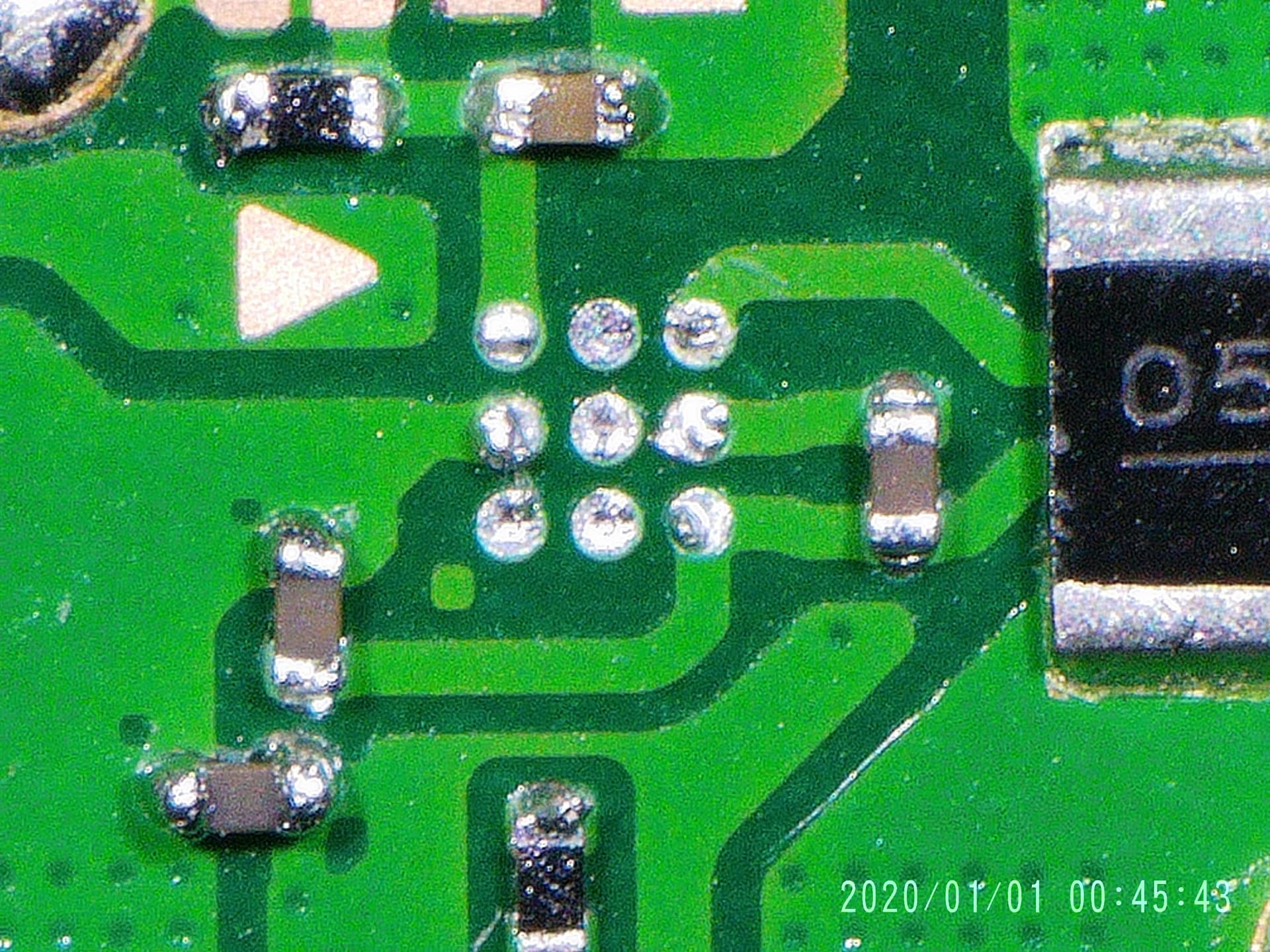
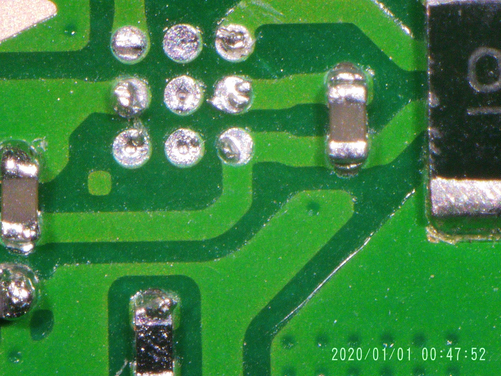
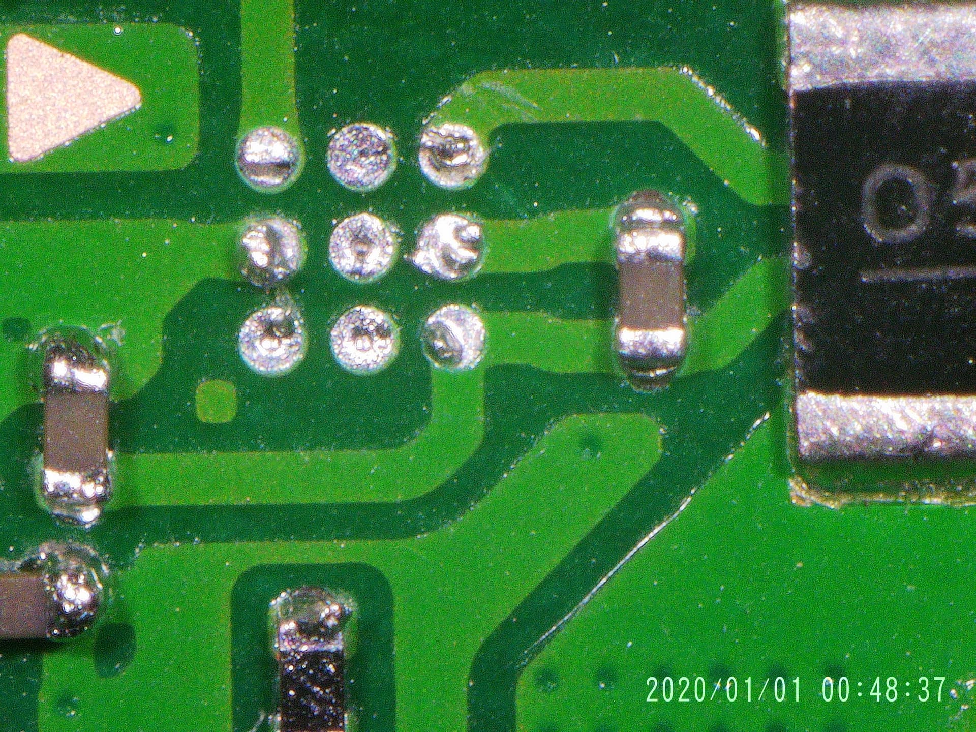
I did accidentally get some solder between those two resistors (or caps?) Circled in red and tried everything with the wick and burned my finger by not using my tweezers to hold the wick (not too bad but quick lesson learned!) but couldn’t get the solder out.
I then applied your tinning method with solder and put the wick near the soldering iron tip (D16 fit the best in this spot) and it sucked it right out. Amazing experience!
I felt like a pro . Bow all I need to do is order a new fuel gauge ic. I found a bunch on eBay but they’re all coming from china and will take a while, are there any faster source where I can multiple and for cheap?
Also, I foot a much better feel for my hot air and iron. After watching tons of YouTube videos and applying what I’ve learned here, I found ways to apply the heat much more efficiently and was able to quickly remove the ic before causing damage anywhere else.
On my practice board, as I took off similar ic, I accidentally knocked resistors off and this was a quick lesson too to be extra careful and to make sure to have a good enough angle to come in at.
Caps will typically be a shade of brown and resistors will typically be black and an ever so slightly lower form factor.
I’d avoid buying these from China, the last batch I got they were either clone chips or they were all used and reballed… or both. You can pick these chips up on Mouser or Digikey, maybe Element14 / Farnell all of which are legit distros
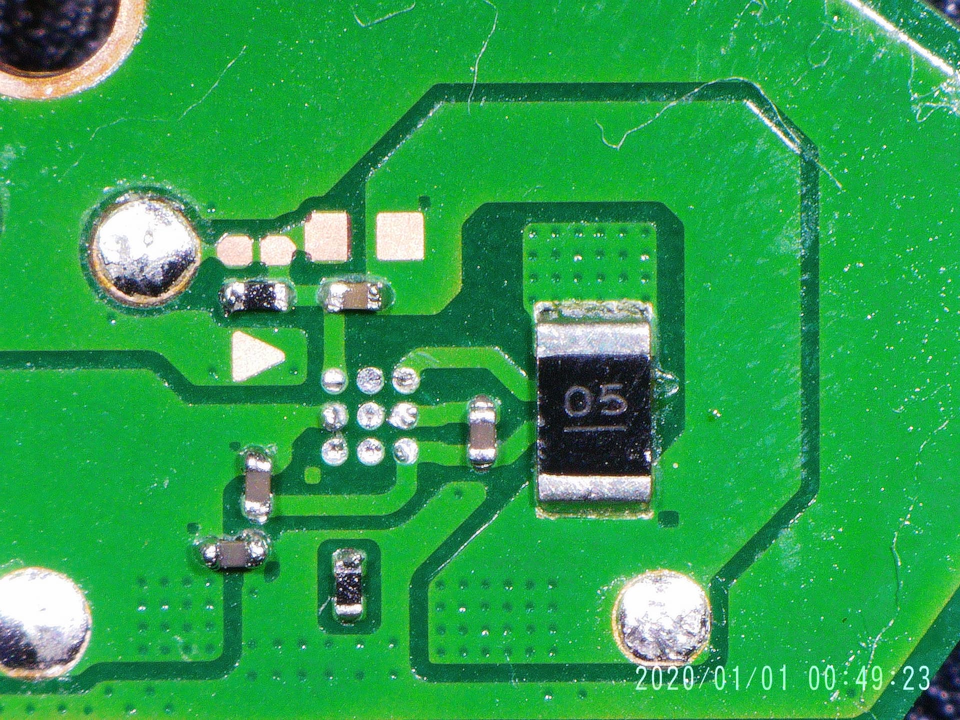
btw in that picture, I don’t know if that’s what it currently looks like - in general it’s good but I’d take another pass of the pads, you can tell they haven’t fully cleaned up as I can see the cotton swab fibres have caught on the jaggies, these will make your life a little harder when placing the IC so if you can get it to the point of not leaving those cotton fibres you’ll know the pads are cleaned up enough
As for the excess solder on the passives, just touch your iron to the joints with flux etc and just wipe your tip off every other time, clean, rinse, repeat until a nice joint is made, saves the wick
Just remove the caps (or one should be enough) with tweezers and hot air, then put it back or Grab a fresh one from a donor. Then the excess solder should not be bridging anything (if some sticks on the ends of the resistors it doesn’t matter)
Wish you’d have said, I’d I’ve told you not to waste your money… your can buy a real microscope for < than that though to be fair this does seemingly does have semi decent image quality for a lowly digitial
Good luck with it, Image quality is good, but it is way to close to the board (you can increased the distance a bit with some manuel mods, but soon the Image gets to small).
I had problems with putting my Iron or hot air under it. (another Andonstar microscope)
The Problem is the small screen, if you Could connect it to a TV it would be no problem
Looks like your Model has a HDMI output, so should be able to connect to a Bigger Monitor, then put the microscope on a higher stand.
I also hate the metal stands, they uncomfortable for the hands and they absorb the heat
What do you recommend? I bought it off Amazon, so I could easily return it for a full refund.
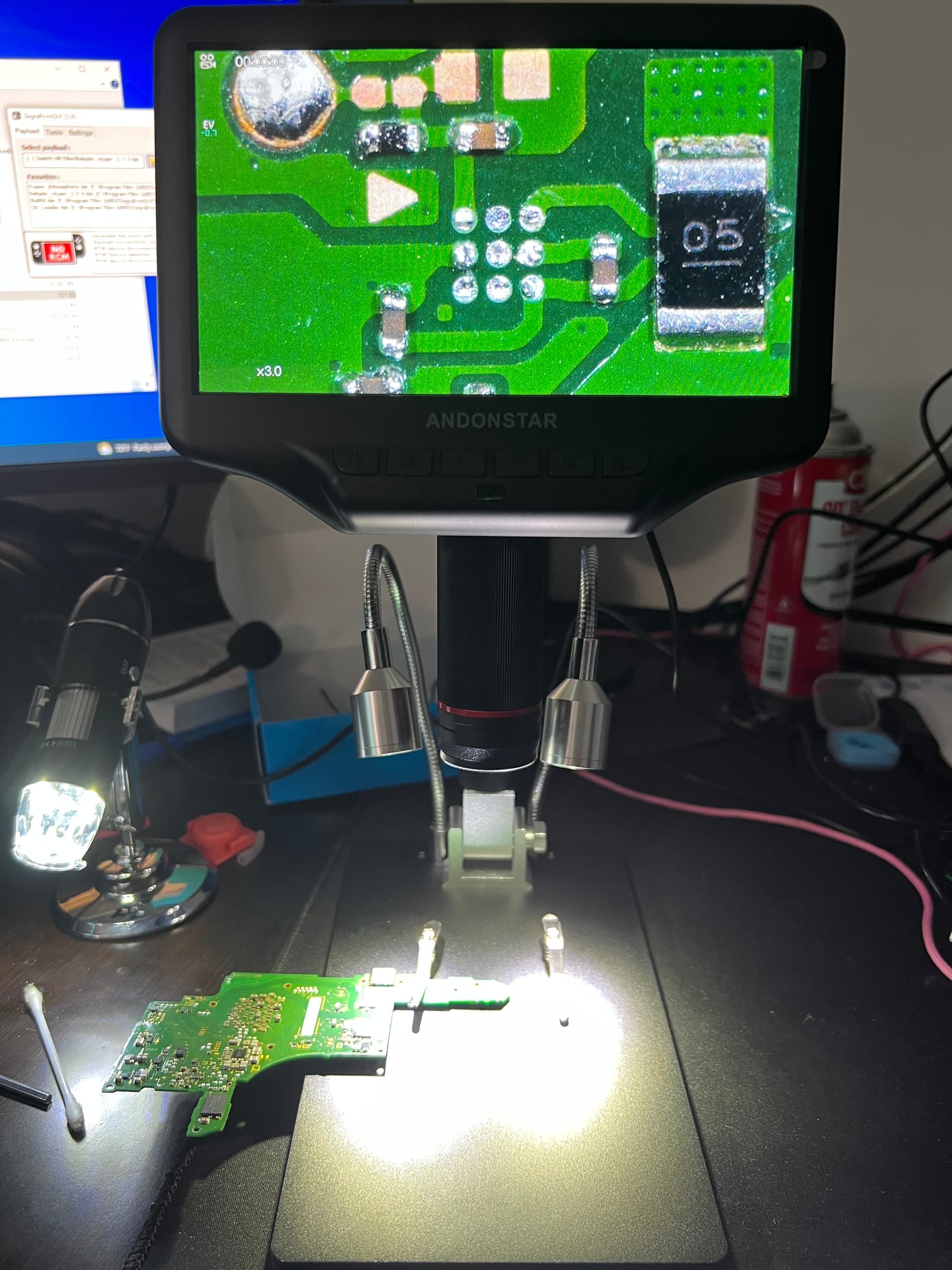
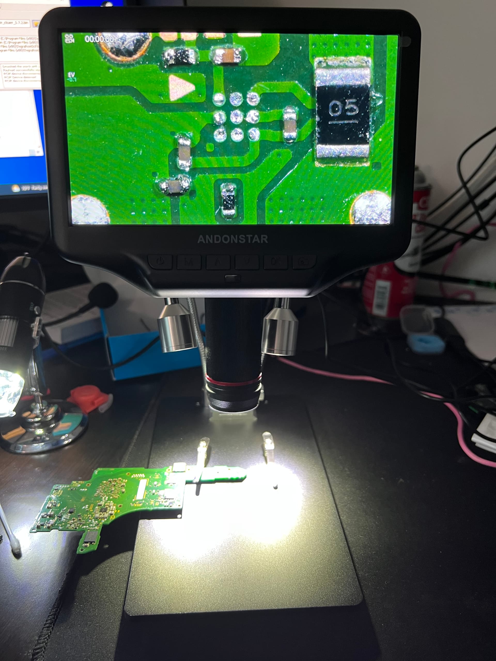
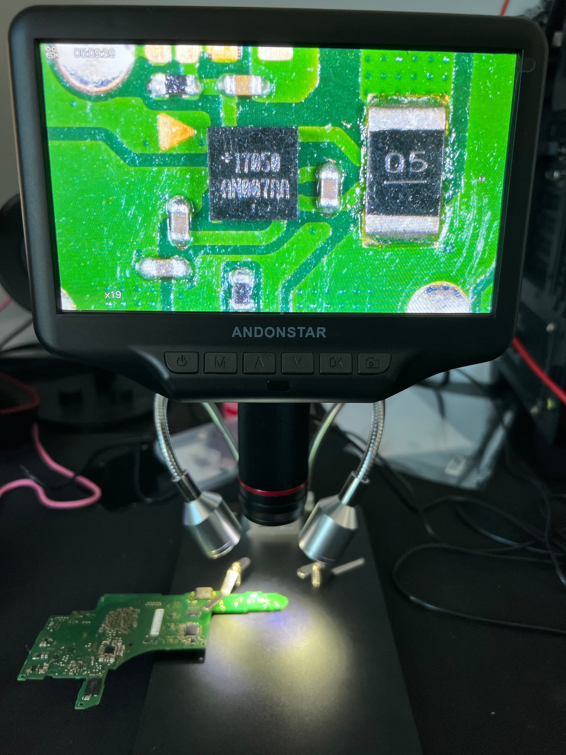
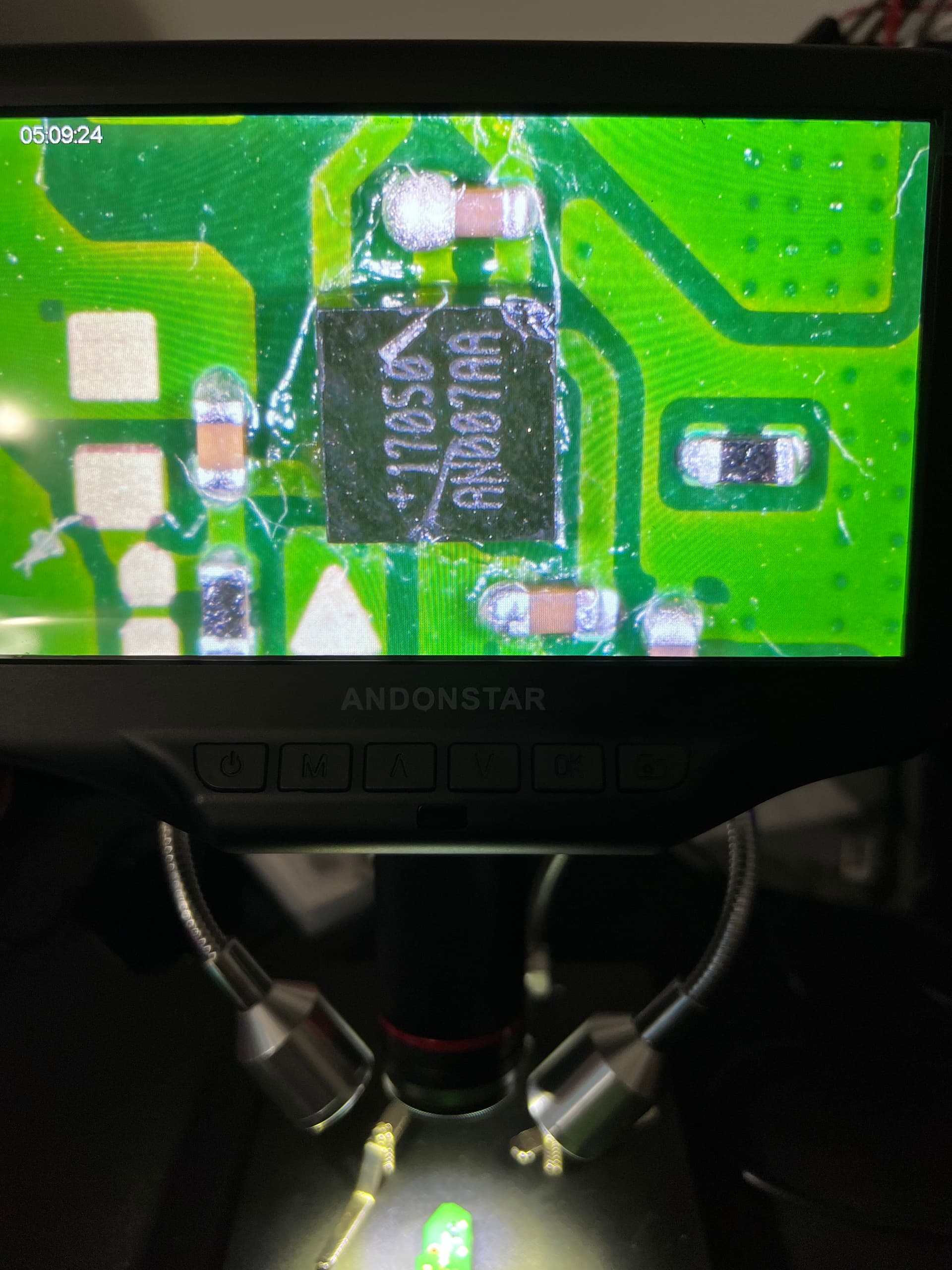
I definitely see what you mean. It just came in and I immediately set it up. I was able to adjust it fairly well when I move the camera/lcd all the way up. I did some research online and found a lens attachment for about $11 that will give me a much better FOV. I saw the reviews and a lot of them were from people who bought this AD407 and highly praised it. Should come in in a day or two I’ll upload some photos.
I was able to move the camera as high up as possible and use the remote to zoom in, imo it didn’t seem all too bad. Here’s a pic of it zoomed vs not zoomed.
I have to say the stand is firm and sturdy, haven’t heated it yet, but definitely too small.
I’ll take some snaps from the camera itself and will upload here. I have to say I’m quite impressed with the image quality. It’s definitely super clear and sharp. Have no real experience with anything else so idk how this compares with others. I did a lot of research online, this was what I found. They have another AD409 but that’s $400. No Ty lol
I don’t think these snapshots are doing it justice. I think the quality is actually better on the lcd itself. (ironic) The video quality is amazing. It’s weird the photo quality itself isn’t as sharp. Either way, It’s not bad. If i could get something better in the same price range though, I’m all for it.
These are a combination of the camera being as high as possible with a 3x zoom, compared to the camera being as low as possible with no zoom. And then just a overview look with no zoom.
I just bought a hdmi microscope camera from aliexpress, cost about 100-150, then you still need a Monitor, I just have a 24 inch Full HD you can basically for free
I made a few posts here on the subject so I won’t rehash but a trinocular microscope, better hand eye coordination, quality among other things, the ones from China (that I covered in the other topics) are identical to the Amscope/Swift versions, so if you don’t mind the wait (and the other things mentioned in the other topic/s) then opt for that. As Johnny_debt mentioned with a trinocular you have the option of adding a camera later.
The image quality on these for a digitial is excellent, I would love to know what sensor they’re using in this but there is no information online about it… I would imagine the sensor version is likely printed on one of the PCB’s inside much like the more standard cameras meant for the trinocular. If we could figure out the sensor then you could probably find the more standard variant which easily fits a trinocular scope. I wonder though if the perceved decent quality on this camera is more down to a good choice in light above anything
I looked up trinocular microscopes and couldn’t find any with enough space to work with pcb’s, but i did find others that did, with the big arms, but those were minimum 400. Also, there seems to be so many variations, seems like there a lot to learn to know which one would be the best bang for the bucks.
You can probably find it cheaper (I’m not a fan of this seller/company but the product is good) so look around. (for reference and when I got mine a few years ago, I paid 160 quid delivered all in, to give you some idea)
As I mentioned in the other topics, the stand is a bit rickety and there is no bearing for the rods, so sliding in and out is not smooth but other than that it’s functional and you can also just bolt the vertical rod straight into your workbench directly instead… alternatively you can get one of thos fancy cast iron stands for this scope but they cost fortune and seriously bump up shipping costs
I finally got around to installing the new max17050 and it still shows a blue screen
Did I install it wrong or could there possibly be a RAM issue? How do I confirm whether or not I installed the IC correctly? Caps around the IC do not come up as shorted, I’m kinda disheartened
I took another pass at it with the hot air gun. Accidentally knocked one of the resistors off, spent some time learning how to get that back on. And I ended up chipping the IC… sigh
 immensely.
 . Bow all I need to do is order a new fuel gauge ic. I found a bunch on eBay but they’re all coming from china and will take a while, are there any faster source where I can multiple and for cheap?
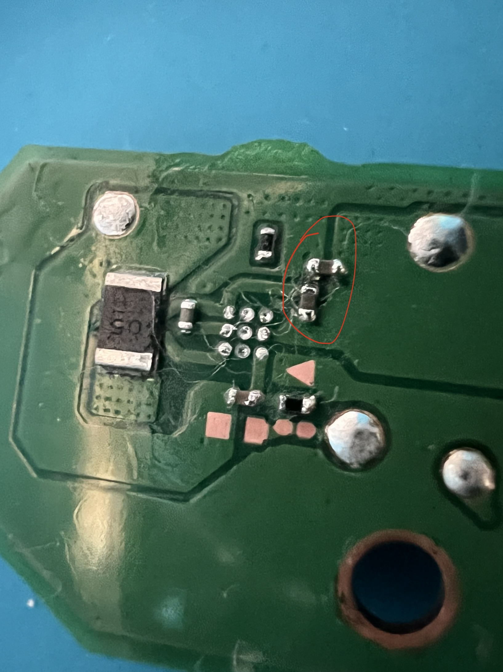
 though to be fair this does seemingly does have semi decent image quality for a lowly digitial