ah, you mean the emmc is not the console’s original one? ok, is there anything else you suggest me to measure before I put the whole thing together again and try biskeydump ?
can you switch your meter over to the 200Ohm scale,… i hate manual ranging meter ![]()
It’s always possible on used or prior repair attempt consoles
haha got it, sorry next time I will use the most precise one for each point
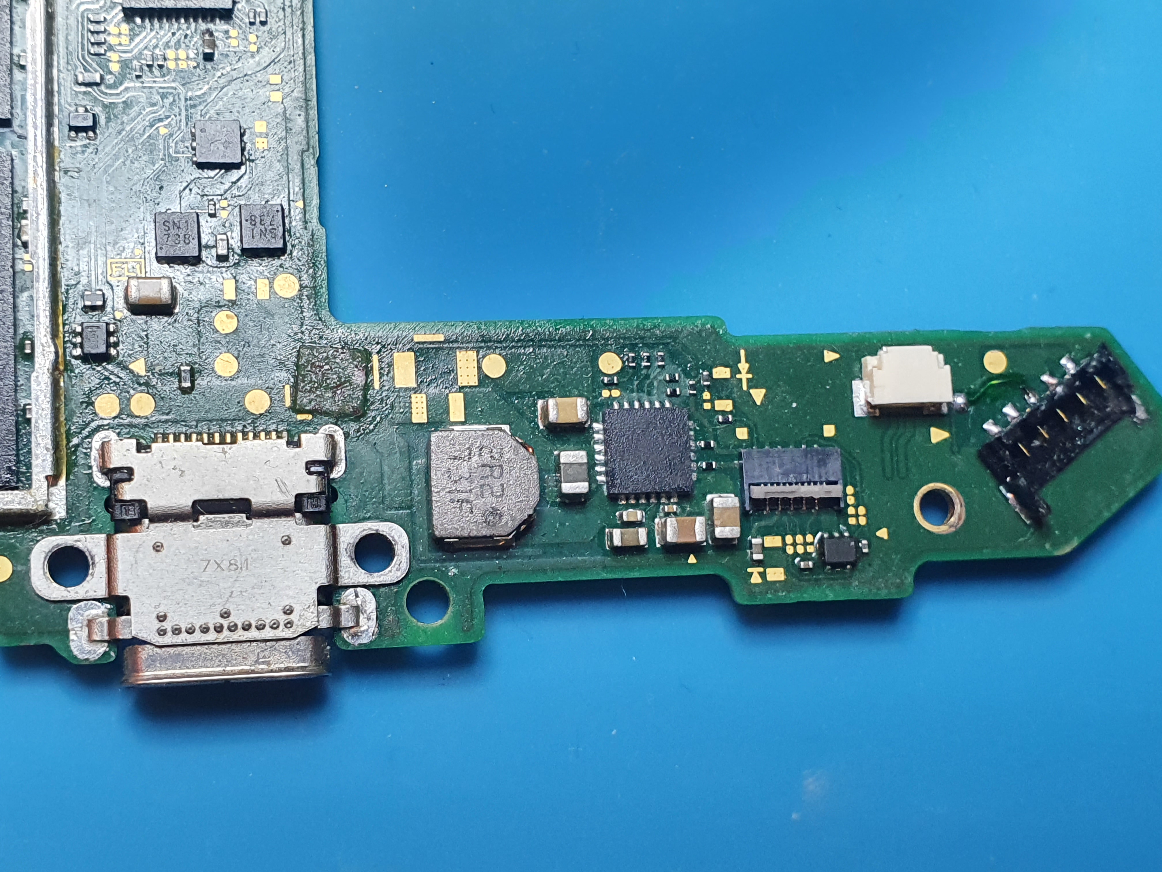
it measures around 60 Ohm here
yea got it, but the point is, at least Linux or Android should work, as they don’t really touch the emmc right?
Right, but they won’t work as a result of the hardware fault/s
I believe this is normal, purple i’ll have to double check
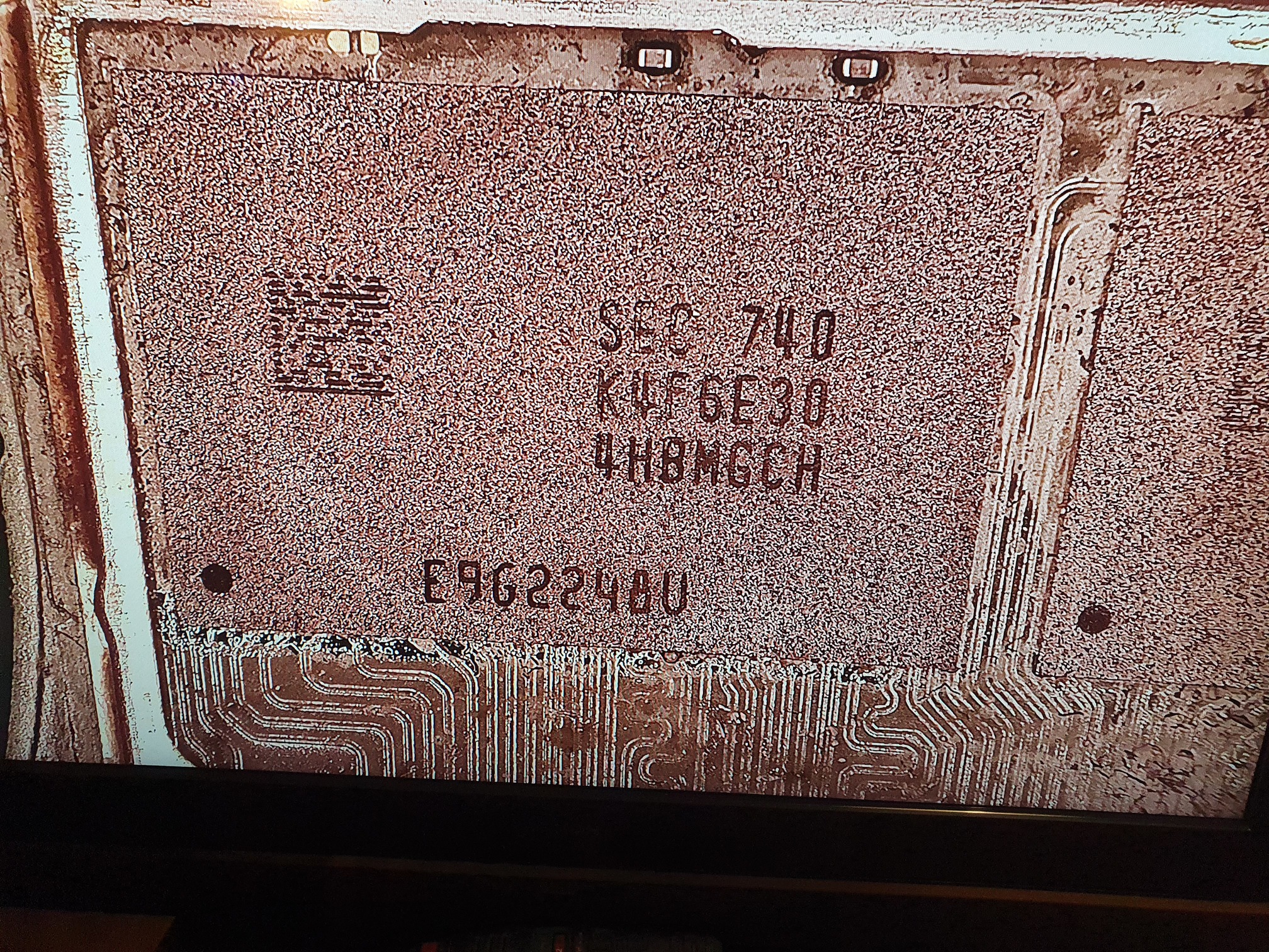
Also, after you’ve checked Biskeydump, can you remove SoC shield and also take a picture of thiis area, want to check if somebody hass messed with Ram
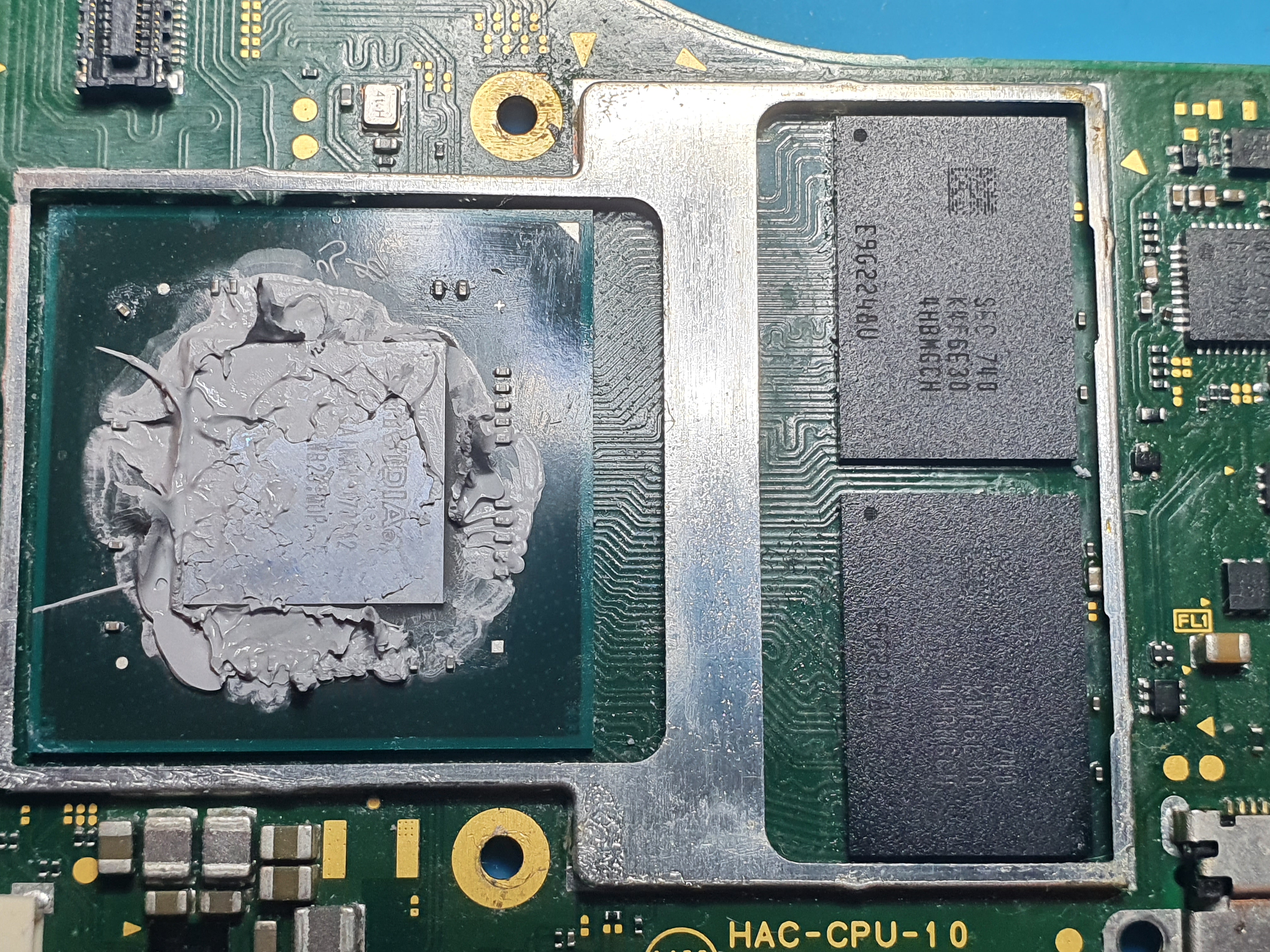

Looks as though the Max IC to the left of SoC has been reworked afaict - flux residue(?)
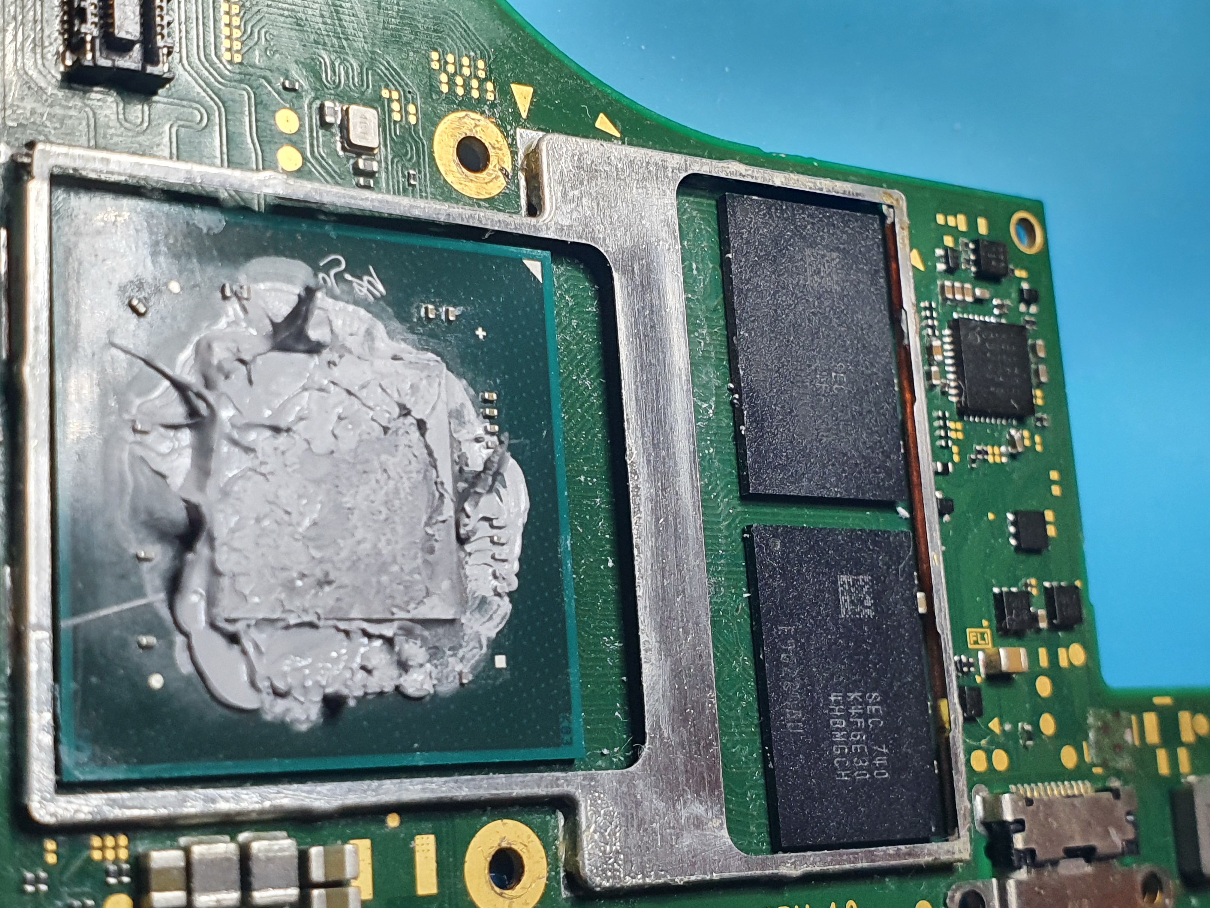
Ram looks to also have flux residue around them.
Either could be the culprit as they both connect to your shorted rail. Now , this is my best guess from looking at your pics, and it’s always possible neither are responsible for the short. If it were me, I’d start by pulling the Max IC off and seeing if it clears the short, if not, I’d pull the Ram IC’s. Word of warning you will require stencils and solder paste to put the IC’s back on (if they aren’t the cause)
Yeah
the meter reads fluctuating values here as well, all sorts of funny numbers with different settings.
to me it actually looks fine, the board got quite dirty during my own repair process, as thermal paste was accidentally being spread around and I tried to clean off most places with iso and a toothbrush. so maybe some places look messed up but I don’t think someone had taken off the max ic or the ram before. but I am not 100% sure especially about the ram since the shield has been removed before. tbh ram replacement is something I would sh*t my pants, it requires quite some practicing. you mean stencils for the chips? or the board? are there standard size stencils for switch parts that can be bought somewhere?
Thank you for helping me here, I really appreciate it! =)
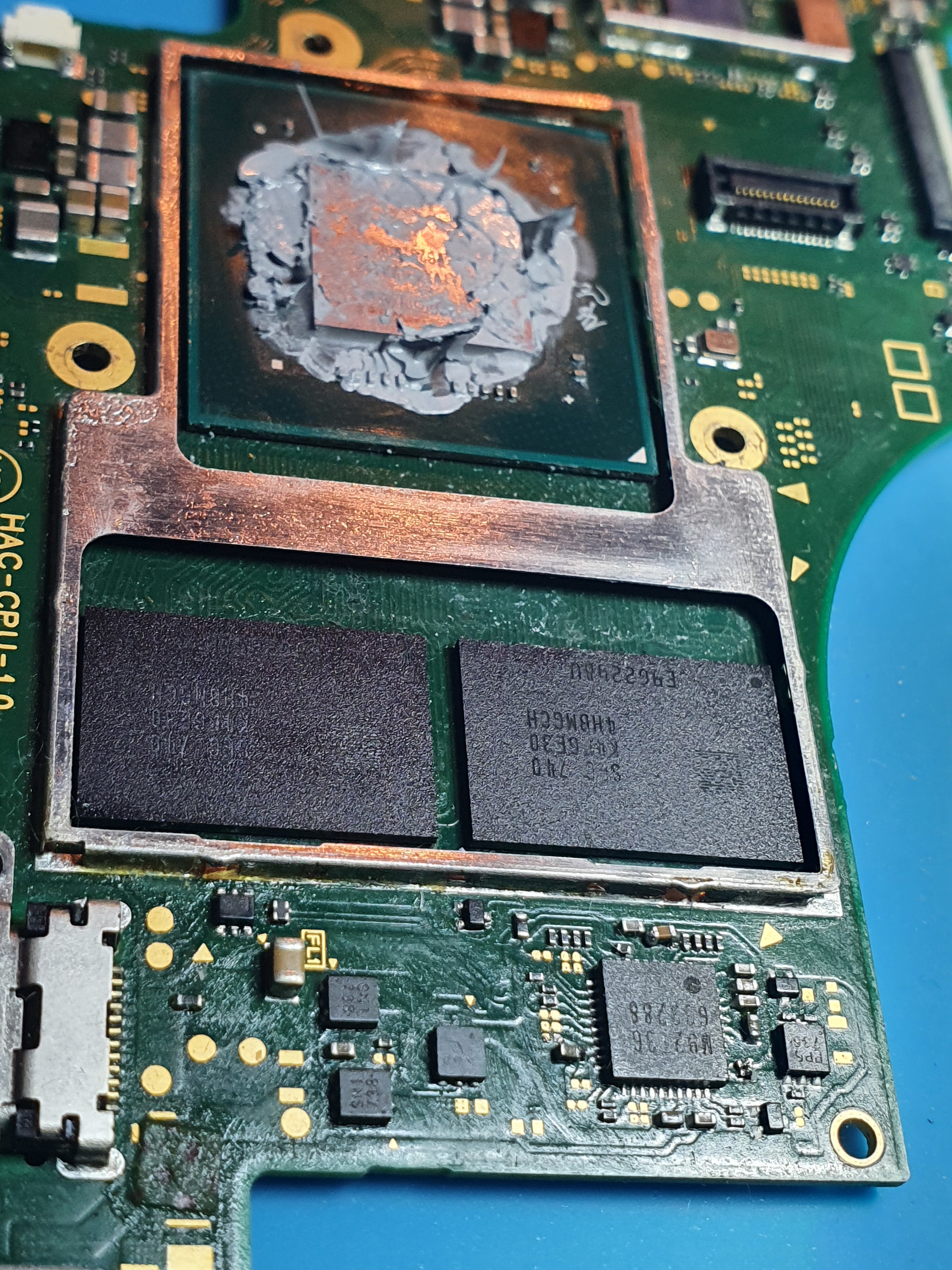
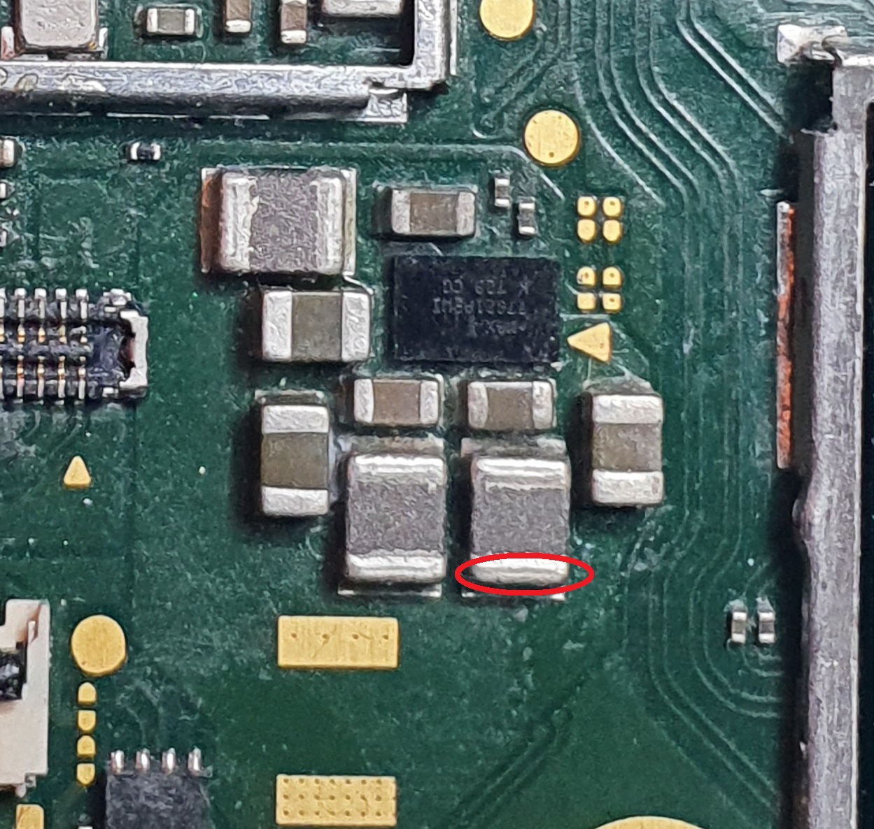
Can you confirm if the highlighted spots are solder balls?
Maybe it’s some other sort of other debris, but if it’s solder, then start by pulling that IC first.
Absolutely, practice removing some BGA IC’s on some scrap/donor boards.
yep, Calvins suggested stencil is a good choice.
You should be getting a relatively stable reading here, do you know anybody who you can borrow a better quality auto ranging meter?
Thanks Calvin, that’s a pretty good thing, in case I’m really going to need it, I know where to look now 
I checked the ram, it was no solder but thermal paste, cleaned it off a bit
Sorry my probes must have been loose, I get around 66 Ohms at the red circled place, @Severence.
Any other suggestions apart from this RAM? I think since this is really advanced stuff, I’d take any chance trying to replace / reflow other possible error sources. 
What voltage do you measure at your shorted cap after booting up Hekate? (careful with your probes here)
Given it’s a dead short, and providing the 1V8PDR is still providing an output (short circuit/OCP hasn’t engaged) then you may be able to feel the culprit getting warm or possibly even hot with just the battery connected.
Failing that you could use a bench PSU to provide the voltage externally.
But it’s possible the culprit has or is on something with large thermal mass and you won’t feel it.
We can only go with the clues from the visual inspection atm, problem is a lot of things on the board connect to your shorted rail which makes narrowing it down diffcult without pulling the IC’s off the board.
okay now I’m getting confused ^^ I measured the voltage and one side of the capacitor (facing m92) has 1.78V (which probably means the power from 1V8pdr is getting there) and the other side of the cap has 0V. Not sure what that means but I suppose thats how it should be? I have a bench PSU here.
I double checked the cap (onboard) and it definitely is shorted (beeping sounds from meter) especially the side not facing m92 fluctuates oddly when measuring resistance to ground.
could you give me some more info about that 1v8pdr? like, if so many things are connected to this rail, would there be other measuring points that I could test? in order to get closer to the culprit? or probably that is what you have been trying already with giving me those testing points? ^^
Yeah, that’s normal, it’s a bypass cap, one side is ground (0V). Though i am surprised it maintaining a voltage of 1.78V…
You could solder a wire to the positive side of this cap, ensure it’s not touching any other point. Connect another wire up to ground somewhere, set your PSU to 0.8V (in case the short is bridged with some lower voltage IO) and set your current limit to 500mA to start with. see if anything gets warm/hot, if not increase current limit.
1V8PDR goes to/powers approx 35% of all major IC’s on the board, off the top of my head, it goes to the EMMC, SoC, Ram, the two Max IC’s, M92 and more, it also indirectly goes to about 60% of all other IC’s in the form of enables and pullups etc.
You could narrow it down further if your meter had a good enough resolution ohm scale, but unfortunately that doesn’t seem to be the case, the alternative would be using your bench PSU and putting your meter in the mV voltage mode and seeing which area reperesents the biggest drop.
sounds good. so 0.8V would ensure that I don’t accidentally fry any other parts, I assume that is the lowest voltage that runs throughout the whole board?
oh, and just to be sure, positive side means the side I am getting those 1.78V right??
do you know where I can find some good schematics of the switch board(s), so I could study them a bit? that way I would also be able to determine parts that would need replacement for possible future repairs, so I could order some in. so far I haven’t found some. or does everyone here draw up their own based on measurements? ![]()
Correct. I don’t know what would be the lowest voltage on the board, but as far as I’m aware, lowest voltage to the SoC is approx 1V, so taking into account any potential overshoot from your PSU, 0.8V is a safe bet (what i typically use/do)
There is none unfortunately, I’ve made a few crude diagrams, but @Calvin has made some excellent diagrams of the switch board, typically detailing diode readings, so you might want to look over his previous posts.
yes.
Also I’m sure it goes without sayig, but disconnect battery and USB while applying power ext with bench PSU
I will say though, depending on what the culprit is, it may not show itself in terms of getting hot, for example, if one of the Max IC’s is responsible for the short, it’s unlikely it will get hot, simply because they are ordinarily high current components