I received a broken Switch LITE (HDH-CPU-02). The owner had plugged wrong cable to the USB port and the pins are now bent. He tried to charge the switch but noticed the battery got very hot.
The battery gave 0 voltage and 279k ohms (between red and black) and 191k ohms (probes reversed). I charged it with a LiPO/Li-ion smart charger and got it to charge about 4.1V/1800mAh. The charging current was about 0.8A most of the time.
I removed the broken USB port and turned on the LITE with the same battery but the display remained black (I hope I didn’t bend any LCD pins this time…). However the SoC shield got hot so the console must have been turned on.
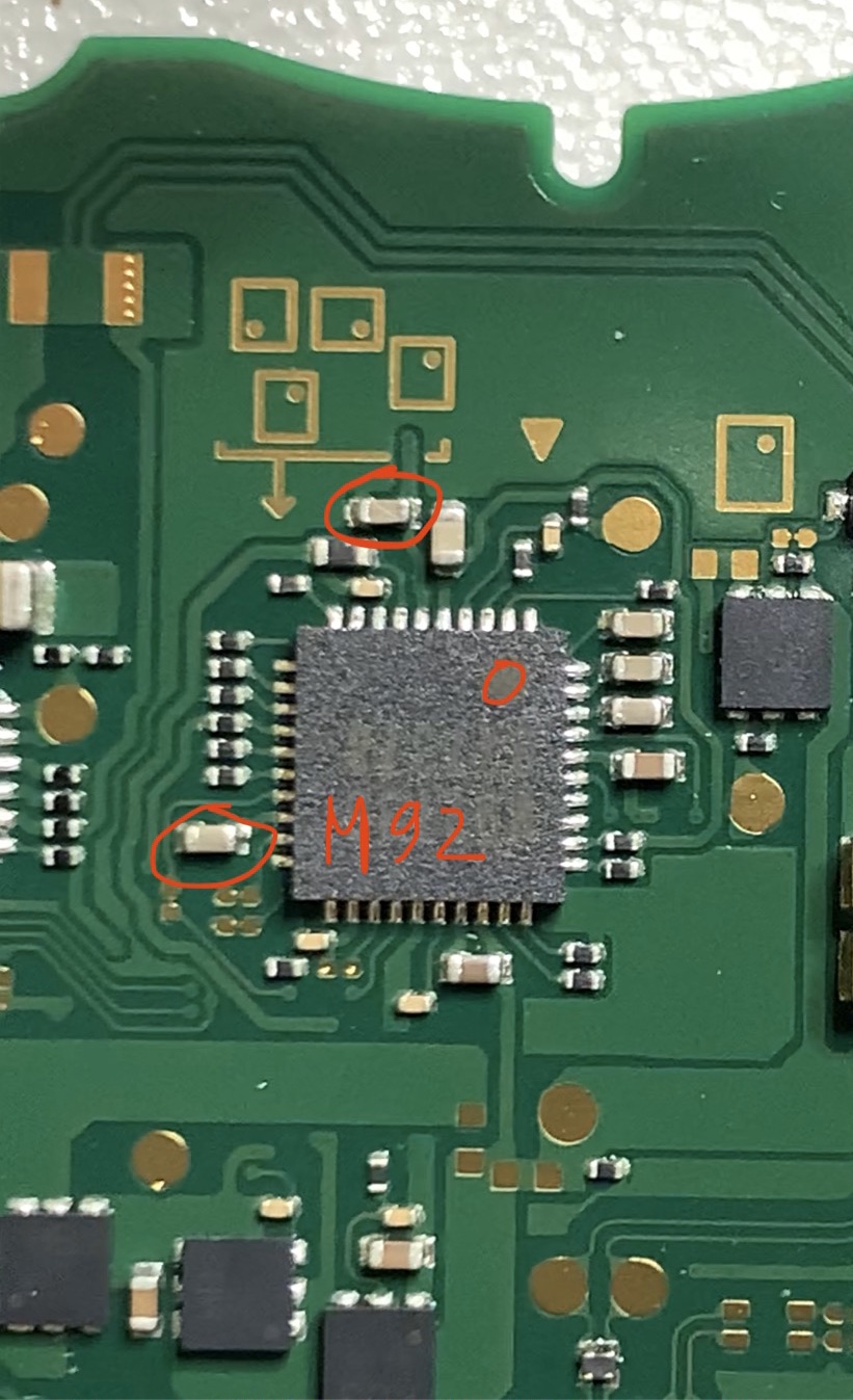
I found that there are two shorted capacitors around M92. This usually affects to the charging but does it also affect to the screen problem? The owner said the console did work even with the broken USB port.
Next, I’m gonna install new USB port and replace the M92 chip. Do you have any suggestions what other troubleshooting should I do?
Hmm if you still have a short there and more specifically the capacitor connected to pin/pad 6 (which is tied to 3V3PDR) even after removing the M9 IC then it’s unlikely to be the BQ IC responsible as from memory it’s not directly connected to this rail… though I’ll have to double check that.
Prime candidates now are the other IC’s which are directly connected to both 1V8PDR and 3V3PDR
Though I can’t rulle out the possibility of it being 2 seperate IC’s/faults IE: an IC that’s only directly connected 1V8PDR with a fault condition and then again on a completely seperate IC which only has a direct connection to 3V3PDR and again with another fault condition… but the chances of this are extremely low, just not impossible. (i hope that makes sense, i know it’s quite confusing)
Same goes for if a cap has failed, but again, the chances of two caps failing on two seperate rails at the same time is very rare.
Unfortunately, the remaining IC’s which are connected to both of these rails “at once” are now all the difficult ones that are not easy to remove/replace… If you were troubleshooting a regular switch, I’d advize disconnecting the EMMC module, unfortunately you don’t have that luxury on Lites, so you may just have to do a visual inspection in the area for now. Paying close attention to the passives and also trying to peak at the Joints below the IC.
I think we can rule out the DC/DC converter which is providing 3V3PDR as it doesn’t have a direct connection to 1V8PDR.
If you can’t see anything obvious around the EMMC such as corrosion or anything else elsewhere then the methods may have to get a bit more intrusive/direct, be we’ll cross that bridge when we come to it.
It might also be worth switching from continuity to resistance and if you have the option of setting the Ohm scale and resolution etc then set it up so it can show the most digits, pick a ground point, then go round the board with the other probe and see which area of the board represents the lowest reading (miliohms) on these shorted rails > in turn the more likely candidate
This Switch was in pretty good condition from outside and I’m quite sure it was never worked on before. I also didn’t find any sign of corrosion or liquid damage.
Do we have any diagrams where I can find what’s on these 3V3PDR and 1V8PDR rails? I can set my multimeter to ohm-range (no milliohms)
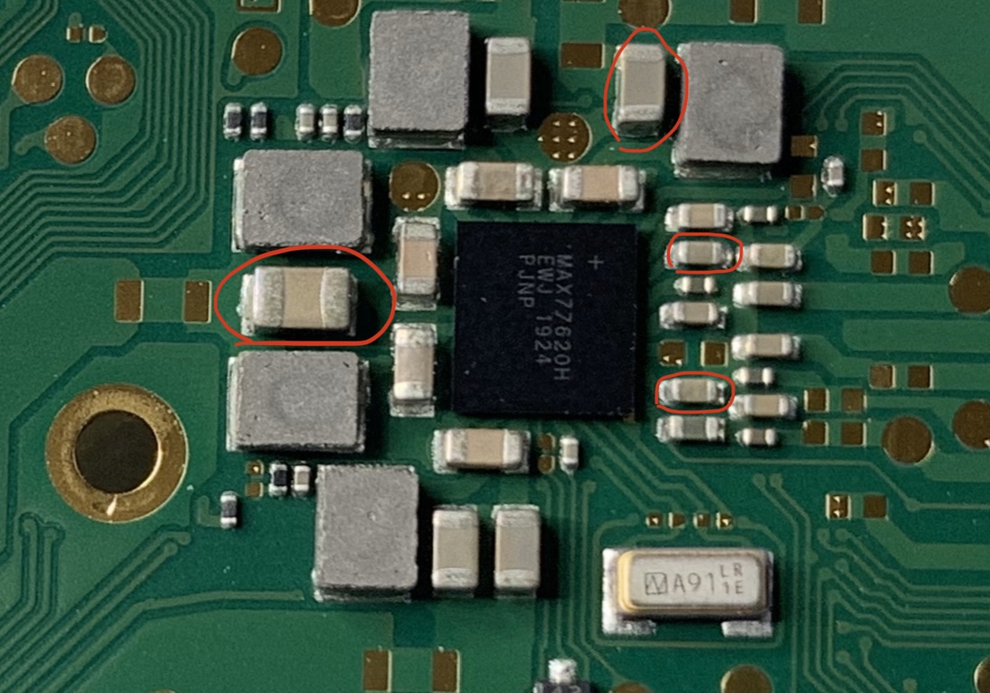
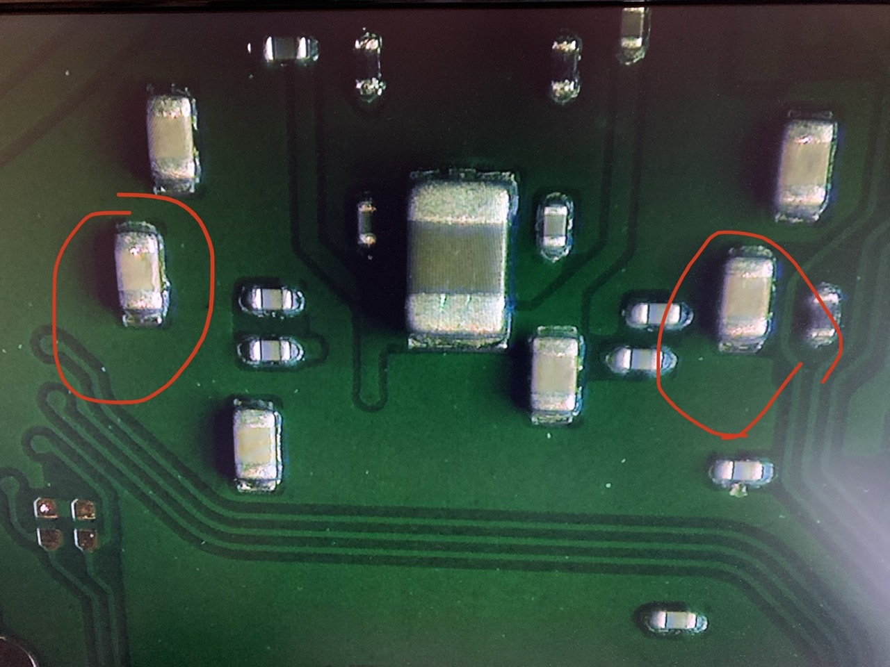
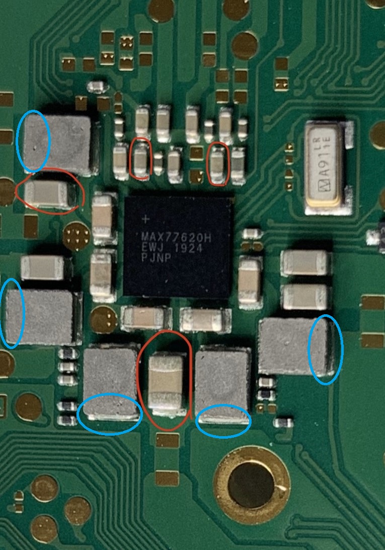
btw, I checked the capacitors around MAX76620 chip and found four shorted capacitors.
The larger Cap middle left in your image likely isn’t short to ground, switch from continuity to resistance, it will likely be somewhere around the 30 to 80 Ohm range. The other highlighted caps are connected to 3V3PDR and 1V8PDR - so given the current fault condition we’d expect these to also reflect a short.
Unfortunately no, as 3V3PDR and 1V8PDR pops up pretty much everywhere on the board it doesn’t seem worthwhile for me to create one…maybe in the future as a boardview i’ll make one.
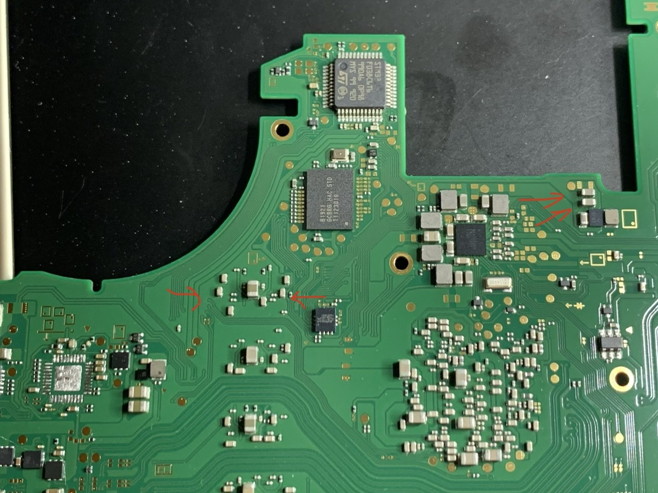
Nothing is jumping out at me in your pics, apart from possibly a solder ball in between a resistor and capacitor above USB.
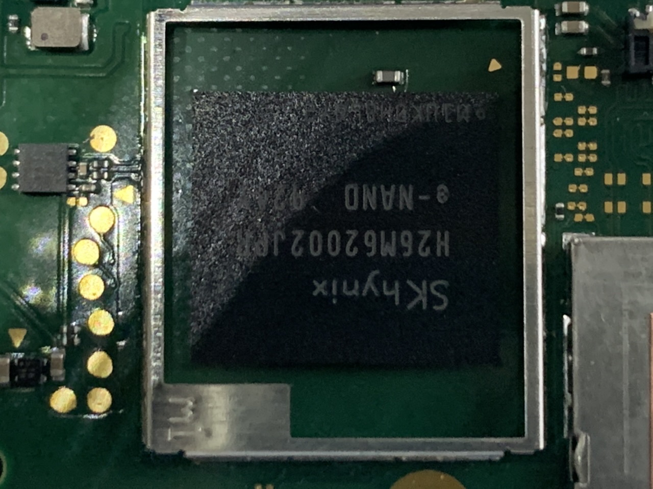
Can you remove the two small shields, one above USB (WIFI) and the other top left of SoC (EMMC)
Also, bear with me, i forgot Lites used a different BQ IC, So maybe it does connect to both rails… i’ll check the datasheet
Probably fine, will likely auto range and hopefully resolution is adequate to show minute change
Hmm this narrows it down considerably (i have the culprit in mind). but bear with me and I’ll get back to you regarding this.
Can you highlight the components which test short to ground here and post the resistance measurements relative to ground on them. As there are some which are normally low here
I don’t see any obvious issues in these photos of EMMC, WIFI. . You can leave these shields off for the time being in preperation for a later diagnosis step.
I’m a bit limited in my ability my end as i only have regular switch boards here currently, and one mariko board (which is extremely similar to lites)
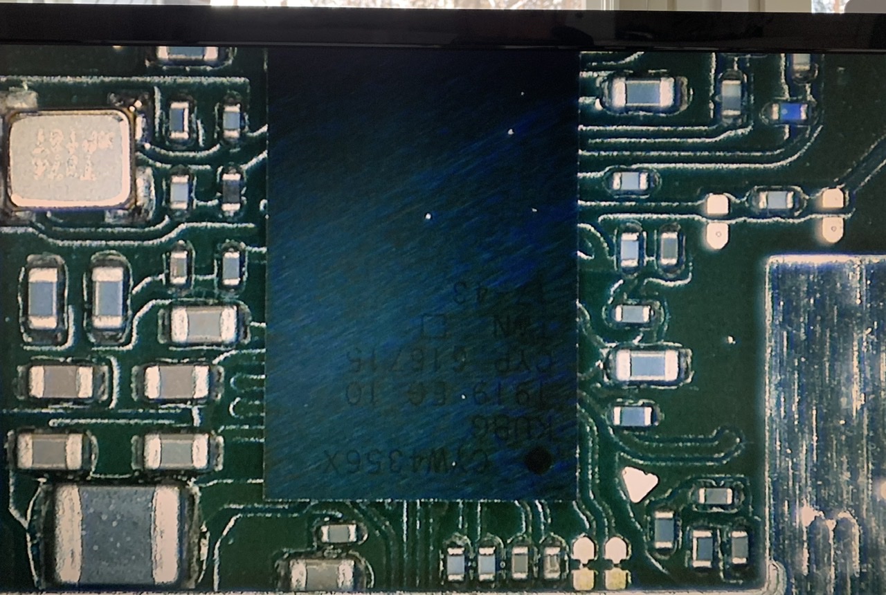
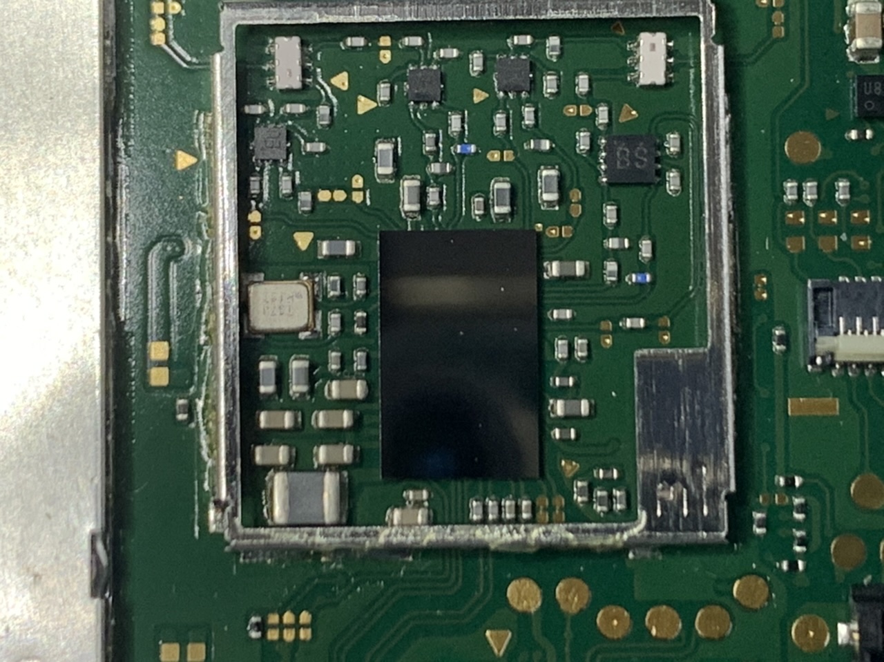
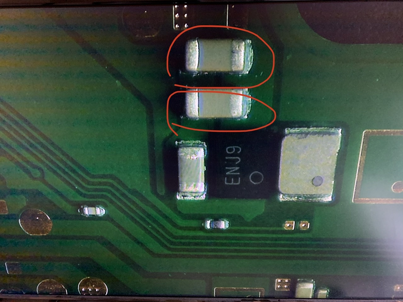
the “ENJ9” IC in your photo is 3V3 DC/DC converter (3V3PDR) and doesn’t have a direct connection to 1V8PDR - so can be ruled out also.
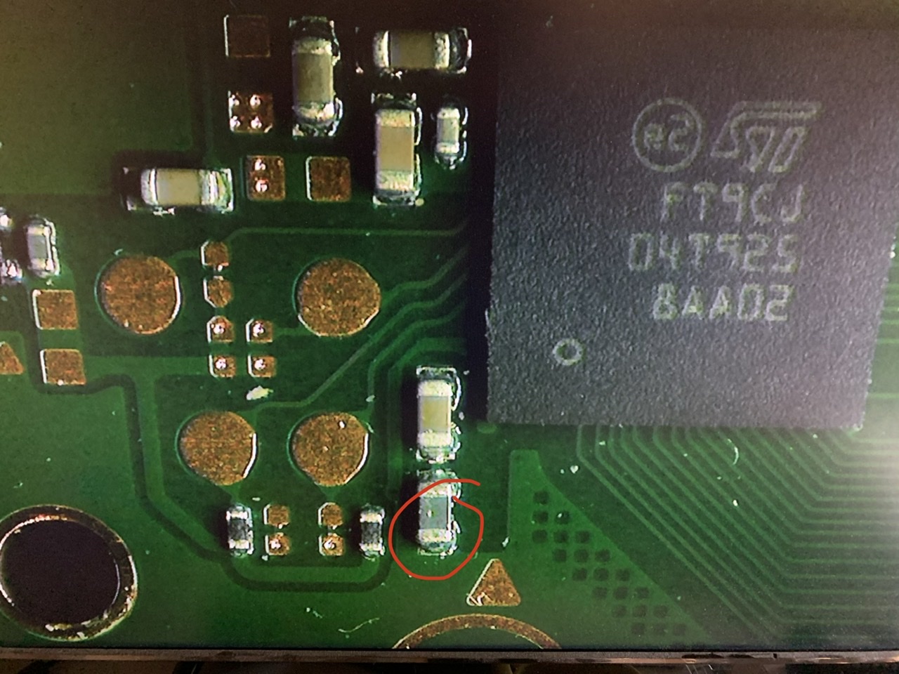
I will have to check specifically which rails go to the ST Digitizer IC (FT9CJ) but given your previous measurements around the PMIC MAX77620 then the ST IC is not a prime candidate (but i’ll check)
All eyes are now on the PMIC MAX77620
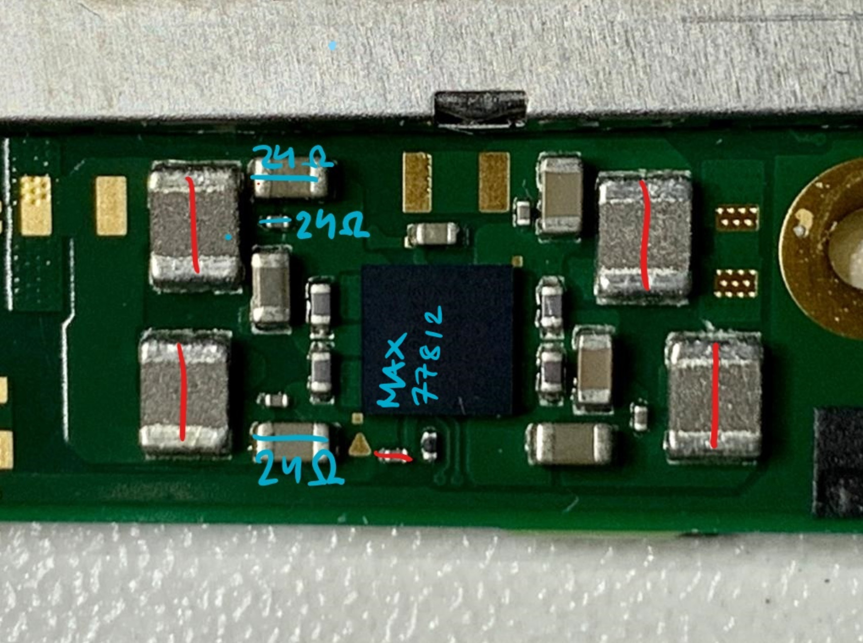
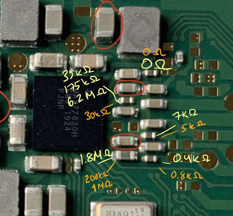
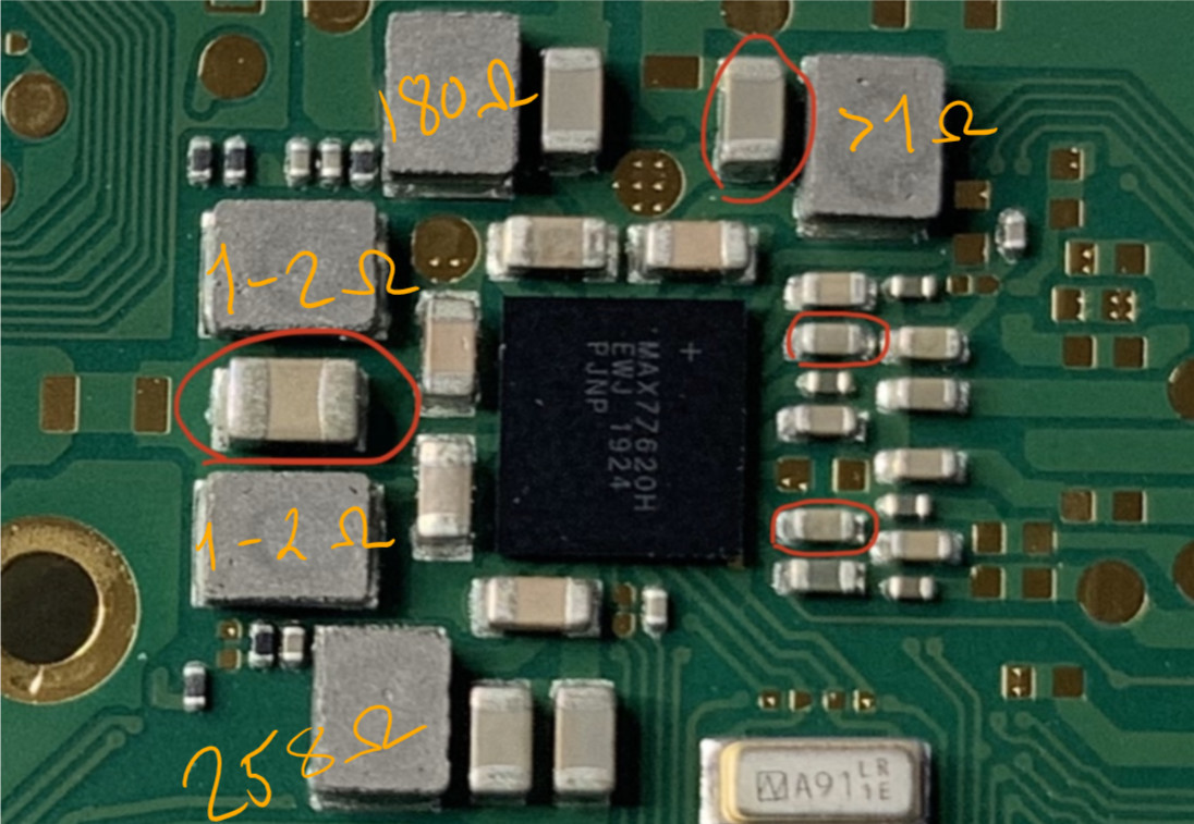
Around the PMIC MAX77620 is 5 inductors (grey) . If you put one probe on ground (screw hole pad nearby is a good choice) and the other probe on one side of each of the inductor (doesn’t matter which side) and then overlay your measurements in Ohms on the image for each inductor we can further confirm the likelihood.
Here are the reactance/inductance values. I measured these several times and sometimes it gave different value. Probably due to the nature of inductor.
Multimeter was set to ohms
Yellow number is the black probe on the ground
Orange is the red probe on the ground
The inductor top right is on 1V8PDR so we expext the shorted reading at this point. (but should normally read in the kiloohms)
The two inductors middle left are on 1V35 rail (from memory… I will have to double check this as it might actually be 1V1) and is normally low resistance but not a dead short as in your boards case.
The higher readings on the inductor top left, and bottom left (representing another two voltage rails) are feasibly correct but again I’ll have to verify this on my mariko board.
As such, prime candidate remains MAX77620. As on a regular switch board it is the only IC (that i’m aware of) that is connected to all three of these rails (1V8PDR, 3V3PDR and the other 1VXX) which are testing as short to ground your board.
But, there’s a wildcard on lites such as the ST MCU which i’m gonna have to rule out with their respective datasheet
btw i made an error earlier and assumed the BQ IC was a different chip when compared to the original switch… Ignore me it is the same IC, I’ve been working on about 10 completely differen products and devices today and my heads a bit spun around. As such, i think we can also safety rule the BQ IC out too
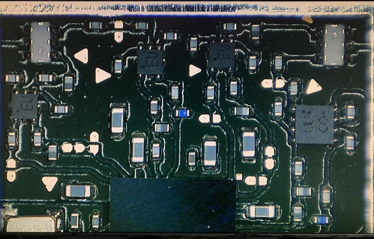
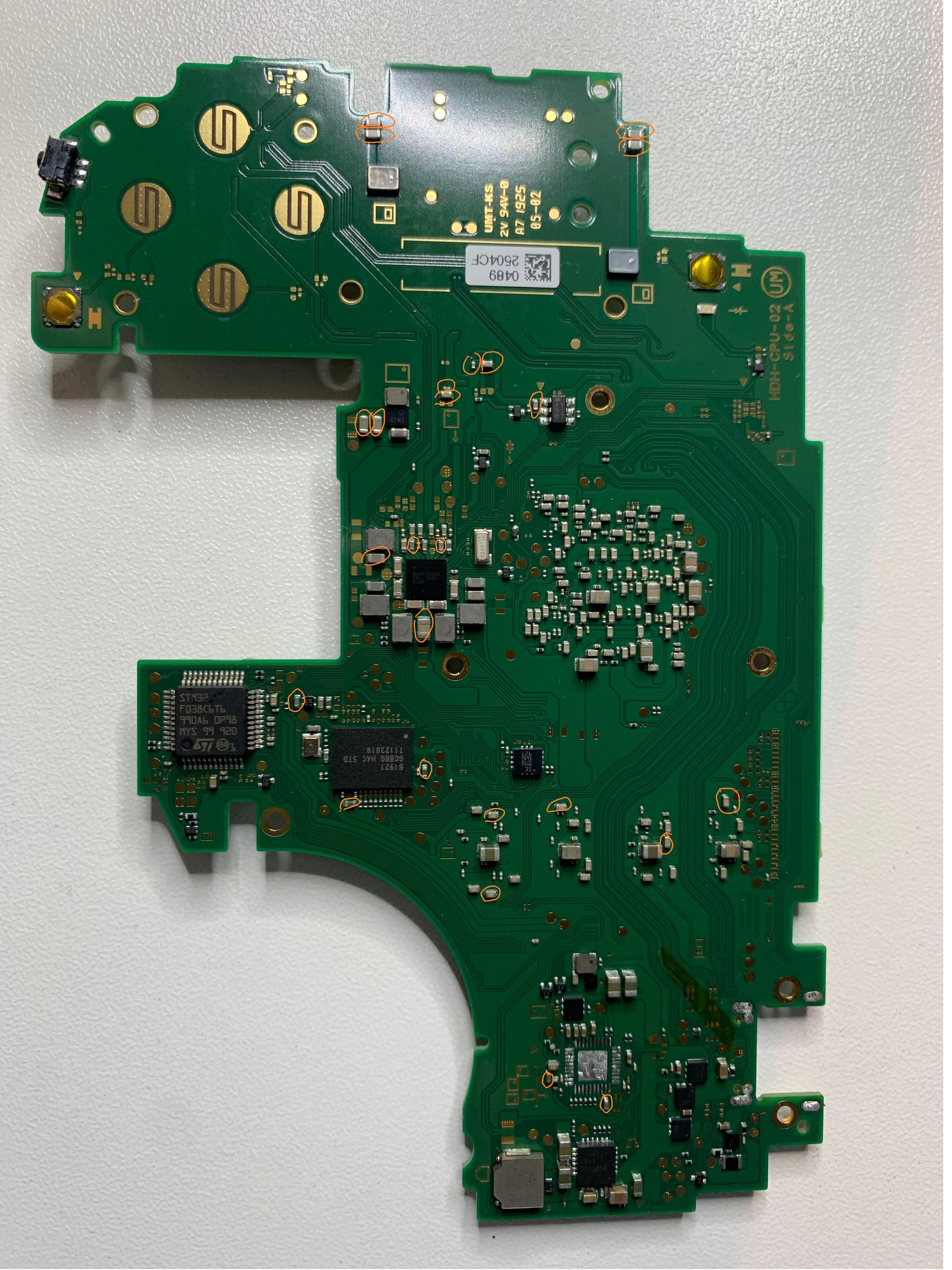
I collected all the shorts into one picture if it is any help. Because of multiple rails shorted there are a lot of shorts all over the board.
I tried finding the short with the resistance method. My meter shows the resistance only in 0.1 ohm scale, so it is quite difficult. I am not very experienced finding shorts without schematics and it’s quite tedious to find and follow the rails.