Switch LITE, USB broken, shorts around M92 and battery dead

There are also several shorts around MAX77812

The larger Cap middle left in your image likely isn’t short to ground, switch from continuity to resistance, it will likely be somewhere around the 30 to 80 Ohm range. The other highlighted caps are connected to 3V3PDR and 1V8PDR - so given the current fault condition we’d expect these to also reflect a short.

Unfortunately no, as 3V3PDR and 1V8PDR pops up pretty much everywhere on the board it doesn’t seem worthwhile for me to create one…maybe in the future as a boardview i’ll make one.

Nothing is jumping out at me in your pics, apart from possibly a solder ball in between a resistor and capacitor above USB.

Can you remove the two small shields, one above USB (WIFI) and the other top left of SoC (EMMC)

Also, bear with me, i forgot Lites used a different BQ IC, So maybe it does connect to both rails… i’ll check the datasheet

Probably fine, will likely auto range and hopefully resolution is adequate to show minute change

It was about 0.2 - 0.5 ohms, very close to shorted.

Good eye. Thanks a lot! There was a loose solder ball between those components. It wasn’t shorted though but would’ve been deadly in the future.

Hmm this narrows it down considerably (i have the culprit in mind). but bear with me and I’ll get back to you regarding this.

Can you highlight the components which test short to ground here and post the resistance measurements relative to ground on them. As there are some which are normally low here

I don’t see any obvious issues in these photos of EMMC, WIFI. . You can leave these shields off for the time being in preperation for a later diagnosis step.

Here you are. My multimeter has softer buzz when there is low resistance.

Red line is shorted ~0 ohms.

Your readings on components in blue are normal.

The four larger components are inductors and will measure virtually zero when measuring directly across them, so readings are good here too.

The smaller cap just below the IC thats measuring as a dead short is on 1V8PDR also, so is expected in your case.

Think it’s safe to rule this Max IC out. and it’s extremely unlikely to be the cause.

Thank you. I was suspecting that also. There is also one more low resistance capacitor which I didn’t mark.

This is a little bit of goose chase but here are few more shorts on (most likely) capacitors

I’m a bit limited in my ability my end as i only have regular switch boards here currently, and one mariko board (which is extremely similar to lites)

the “ENJ9” IC in your photo is 3V3 DC/DC converter (3V3PDR) and doesn’t have a direct connection to 1V8PDR - so can be ruled out also.

I will have to check specifically which rails go to the ST Digitizer IC (FT9CJ) but given your previous measurements around the PMIC MAX77620 then the ST IC is not a prime candidate (but i’ll check)

All eyes are now on the PMIC MAX77620 :smiley:

Around the PMIC MAX77620 is 5 inductors (grey) . If you put one probe on ground (screw hole pad nearby is a good choice) and the other probe on one side of each of the inductor (doesn’t matter which side) and then overlay your measurements in Ohms on the image for each inductor we can further confirm the likelihood.

Here are the reactance/inductance values. I measured these several times and sometimes it gave different value. Probably due to the nature of inductor.

Multimeter was set to ohms
Yellow number is the black probe on the ground
Orange is the red probe on the ground

Sorry man, i meant the following, highlighted in blue

The components you measured above are (mostly) caps, not to worry though, those values may come in handy later and will help me compare :smiley:

1 Like

doh!
And that one value should be <1 (not >1)
Hmm… two have too high value?

Thanks :slight_smile:

The inductor top right is on 1V8PDR so we expext the shorted reading at this point. (but should normally read in the kiloohms)

The two inductors middle left are on 1V35 rail (from memory… I will have to double check this as it might actually be 1V1) and is normally low resistance but not a dead short as in your boards case.

The higher readings on the inductor top left, and bottom left (representing another two voltage rails) are feasibly correct but again I’ll have to verify this on my mariko board.

As such, prime candidate remains MAX77620. As on a regular switch board it is the only IC (that i’m aware of) that is connected to all three of these rails (1V8PDR, 3V3PDR and the other 1VXX) which are testing as short to ground your board.

But, there’s a wildcard on lites such as the ST MCU which i’m gonna have to rule out with their respective datasheet

btw i made an error earlier and assumed the BQ IC was a different chip when compared to the original switch… Ignore me it is the same IC, I’ve been working on about 10 completely differen products and devices today and my heads a bit spun around. As such, i think we can also safety rule the BQ IC out too

I collected all the shorts into one picture if it is any help. Because of multiple rails shorted there are a lot of shorts all over the board.

I tried finding the short with the resistance method. My meter shows the resistance only in 0.1 ohm scale, so it is quite difficult. I am not very experienced finding shorts without schematics and it’s quite tedious to find and follow the rails.

And here is the other side of the board. I am not sure what the shorted components are in the eMMC area.

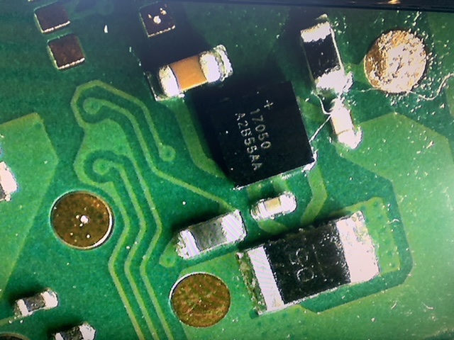
Did you rule out the max17050 fuel gauge chip? No shorts on the caps but there is continuity between the large pads of Q5 component. I think it’s a power resistor and there is continuity also on non-mariko board
image

Sorry for pouching a thread but I’ve looked for answers else where and nothing comes close to my problem, as with this post - some of the caps I have are shorted but some of them are not, I’m copied every test on this thread and replicated most of it some values are different and some caps are not short where yours are short… did you manage to get to the bottom of this?

Switch came in for a no charge / damaged port, I applied a new port and got it to flash up charging for a split second now it won’t charge at all, the pins are reading voltage from the USB C but I’m not sure where else to look, could it be the MAX77620?

I reckon your Lite has a different problem than mine. I did not find the culprit causing the short yet, however it was not MAX77620.

To get some troubleshooting help, create a new post and show us what components are shorted, please.

Ye mine certainly does it was not charging when it arrive and had no charge in it for me to test, when I replaced the port I managed to get it to charge for all of 20 seconds the charge dropped to 0.18amps now its stuck on the blue screen of death I think my failure point is the APU the pins were mangled when it arrived, not even sure if it was BSoD on arrival I’ve triple checked everything so I’m 90% that my repair hasn’t caused it. I don’t use a lot of heat and I use low melt solder which melts are 150-190 so I stick to 200 mainly - I don’t trust my self with 480 temps to not melt the plastic or other parts I mainly use a soldering iron as well rather than a heat gun.

Hi, have You sorted this out? I do have Switch Lite with broken USB port and caps shorted just like in your first post. Removing M92 and BQ dont rule out shorted caps.

Hello,

I have a Switch Lite with a very similar situation. I removed top right coil what confirmed that the MAX77620H chip wasn’t an issue here - the short persisted on the motherboard’s side. I decided to inject voltage into motherboard’s side and sadly, Tegra started to warm up slowly what means it’s the main culprit here.

Hope it helps anyone.

1 Like