So i’ve got a switch that won’t turn on, the symptom is No display, nothing short, only draw 0.4A
I’ve done a few things such as ;
Replacing Battery (still no display), holding power button for 15sec but no response
The switch did detected in TegraRCM but the switch is patched version one so i can’t try the payload method
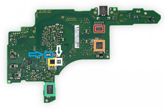
Check all caps around the IC M92T36, BQ24193, and P13USB but no short detected
Fuse and Coil is good (there’s continuity)
I lost a tiny cap above the charging port between the 2 regulator
In desperate attempt i tried to replace M92T36 with a new one but it end up make the current fall to 0A
I notice there’s a shorting cap on the left +MAX 77621AEWI (Between 2 inductor)
Remove the crystal/oscillator in +MAX 77621AEWI area
My Question is :
Did you guys ever encounter this kind of case?
Is there any way to revive this?
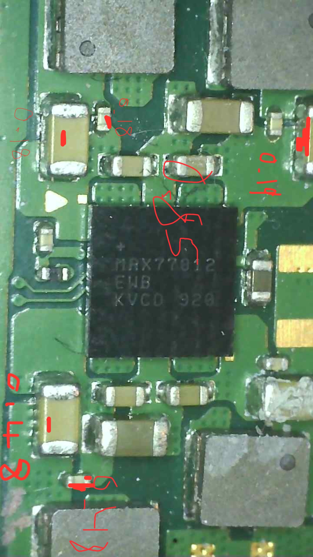
On point 5, does the tiny caps affect the switch? (Yellow box with arrow) *Switch Front.jpg
On point 6, does my new M92T36 is a defect one?, cause if i change it back to the older IC it back to drawing 0.4a
Can anyone confirm the shorting cap on point 7 because it have low resistance or it never been short in the first place? (White box with arrow) *Switch Behind.jpg
I have exactly the same problem with the switch lite I am trying to fix, however I do get a backlight when I plug in the charging cable and measure the amps which are 0.4 amps
It’s a little bit tricky for this case. I’ve been working on this too, but right now i put on hold to this case for i need to working on the other consoles. For the backlight issue you could try to check on the LCD Connector as it often a bent pin on it or you could try this link to GBA temp forum, it’s for “switch 0.4a” case, after he successfully revive the switch he encounter the issue with the backlight, hope you could get some clue on it. If i’ve got improvement for this case i will post it again. for the link just delete the cage
Ah not good… This switch lite was working fine until this happened I was changing the joysticks and they after wards I’ve been getting no LCD show and a backlight with no image, would changing the LCD connector do anything? I have 2 shorts around that area and the max 77620h so I’m honestly stuck at a dead end at this point
Couldn’t say, there’s one in the vicinity of the USB and multiple fusable resistors dotted around the board, including several 0R resistors… one near BQ chip, and of course filters everywhere. If you can take a snap of the component that went missing i can tell you what it does.
If your now getting 0A current draw then it’s bad USB or open component as far as i can think, that includes open IC ie: the M92T36 isn’t soldered properly, If you can solder it on properly we can go from there to try and solve your other issue
I don’t think max 77620 is the issue or the surrounding components. If your getting Backlight but no display i would check the connector has no bent pins then check ribbon.
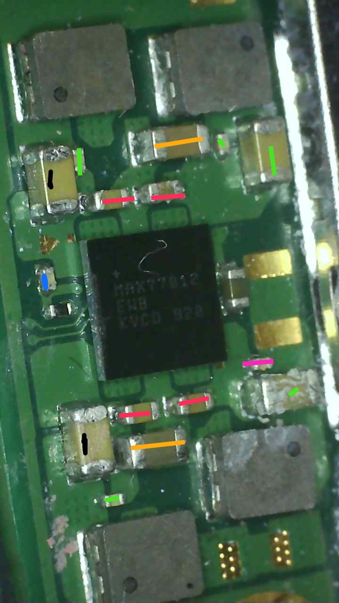
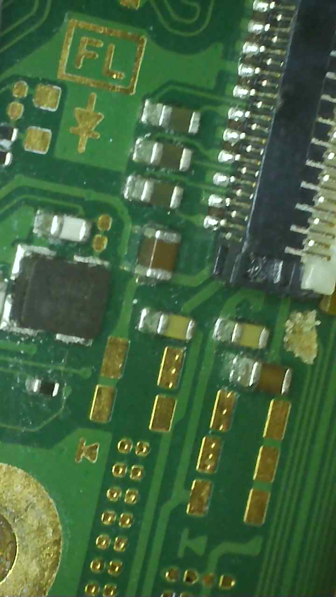
You could also let me know the resistance to ground on each of the coils surrounding MAX77812 (below soc) and let me know, some 0.4A only are caused by this
Roger that il open the Nintendo switch lite and get back to you, I ordered a LCD connector and also I noticed around the LCD connector there are 2 shorts coming up, thank you for you help honestly
Hi there I got the measurements for resistance on the chip like you said, the other resistors are not giving a beep so I assume they are working fine, I notice there’s a pattern on the readings, are they shorted? What does this chip do regarding its function? By the way I’m not getting a backlight anymore but as soon as I put the charging cable in the switch lite the home button lights up for a second.
resistance readings please not diode, set your meter to ohms… diode mode is useless here it’s to vague
take the measurement first with black on ground and red to the positive sde of the capacitor and get the reading then after put the red probe on ground and put your black probe on capacitors positive and take the reading in ohms.
I’m asking you to do the above so i can see if anything is pulling the rail down and i’m getting you to reverse your leads so i can check the impedence / junction/s are good
Think it goes with out saying but just in case, make sure the battery is disconnected.while taking measurements.
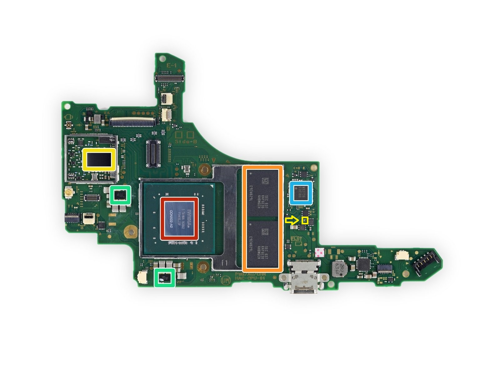
This chip is the equivelent to both of the MAX77621 IC’s on the original version switch boards, in this case it effectivly combines both chips into one. Function wise it generates a 1V rail/s for the SOC, whether this rail is enabled at boot is dependent on the FW version afaict, aside from that though the chip is tied back to the main max > PMIC MAX77620
If there is a communication issue with this chip it can cause the typical 0.4A draw etc
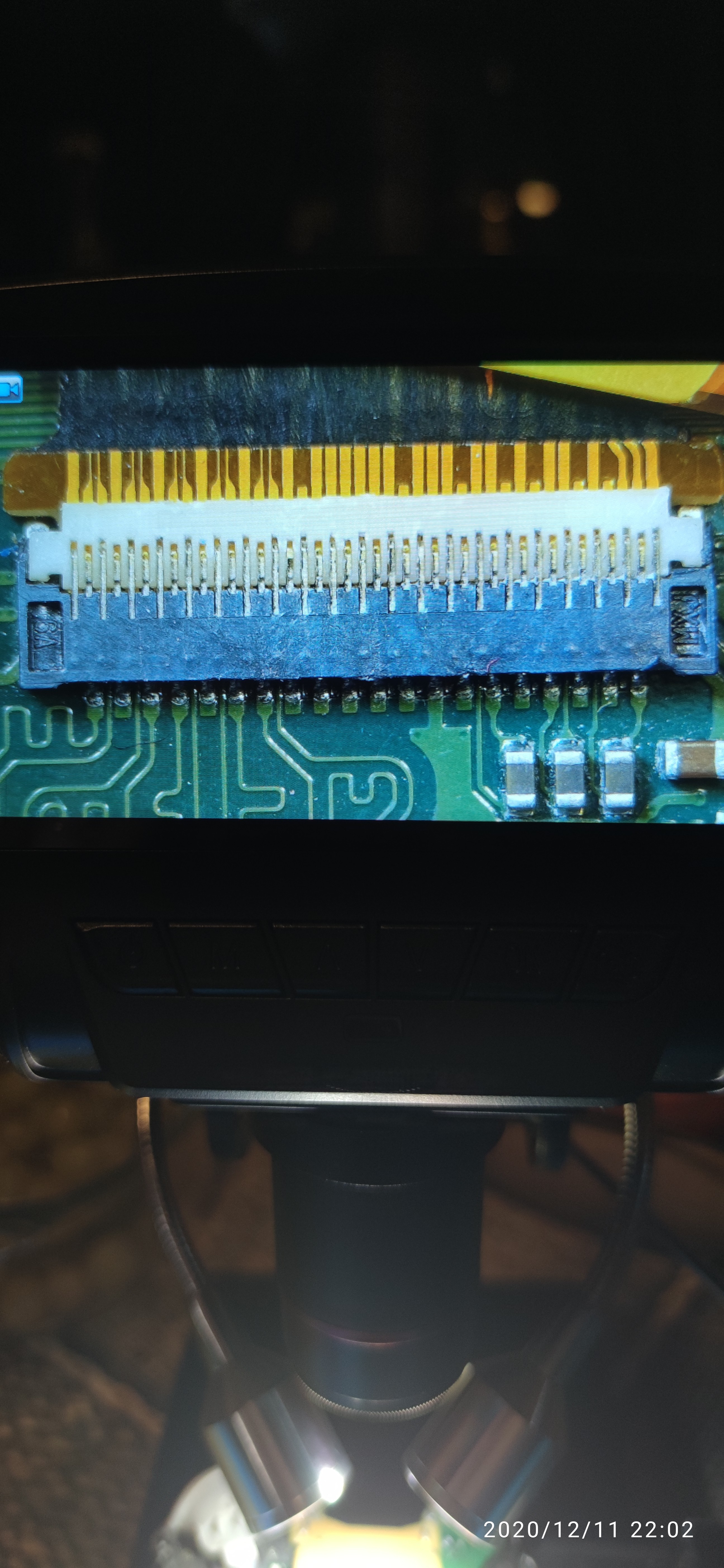
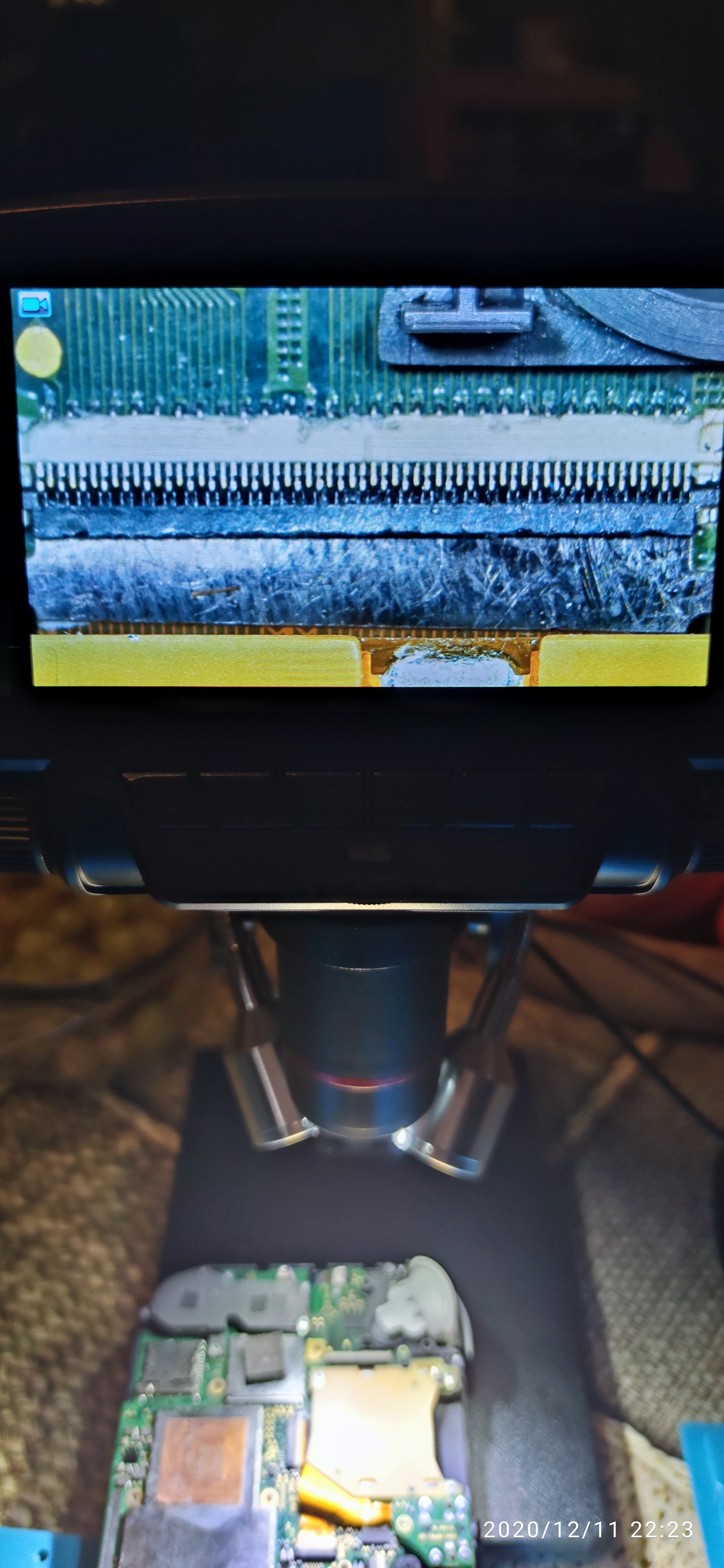
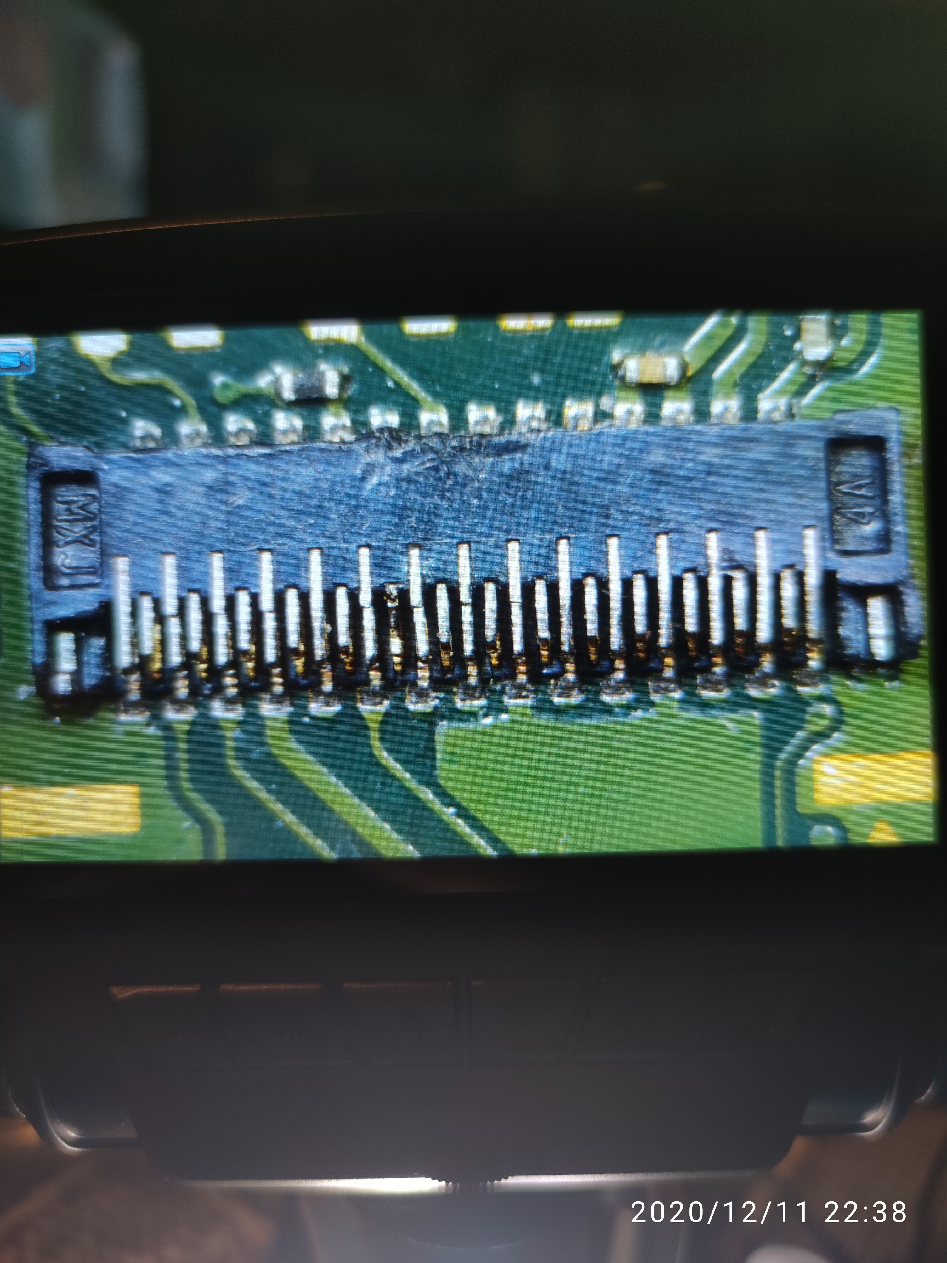
Can you also take a photo of the LCD connector area so i can take a look and also the backlight circuit
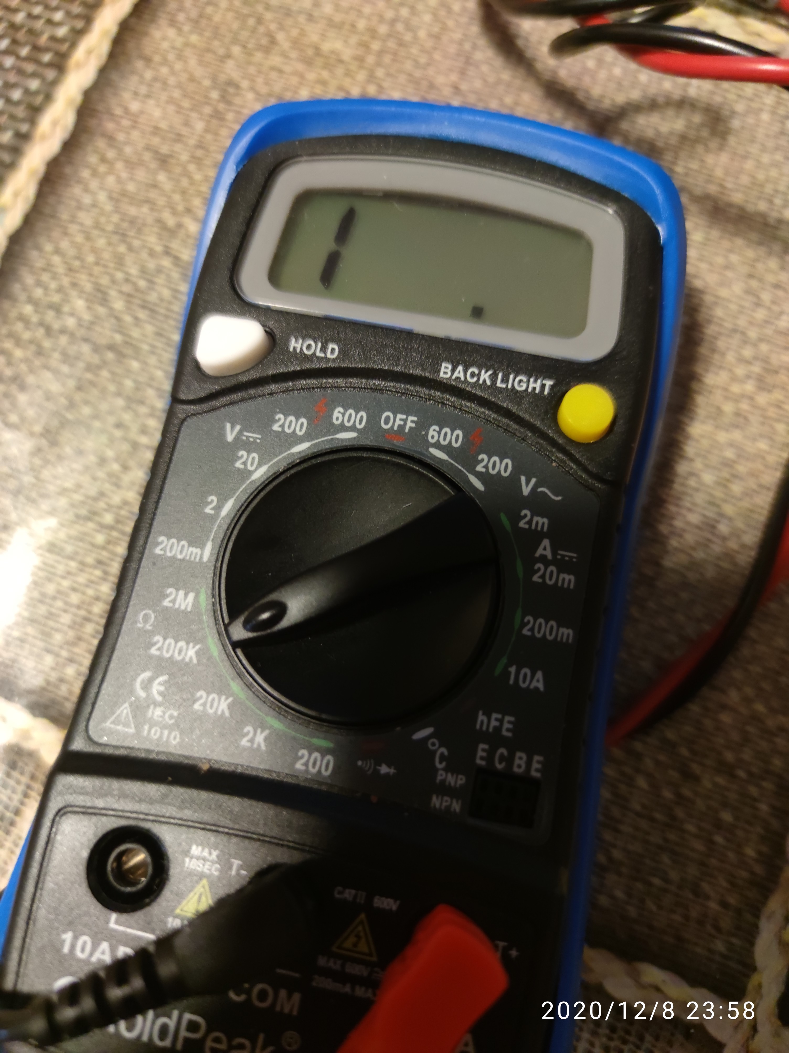
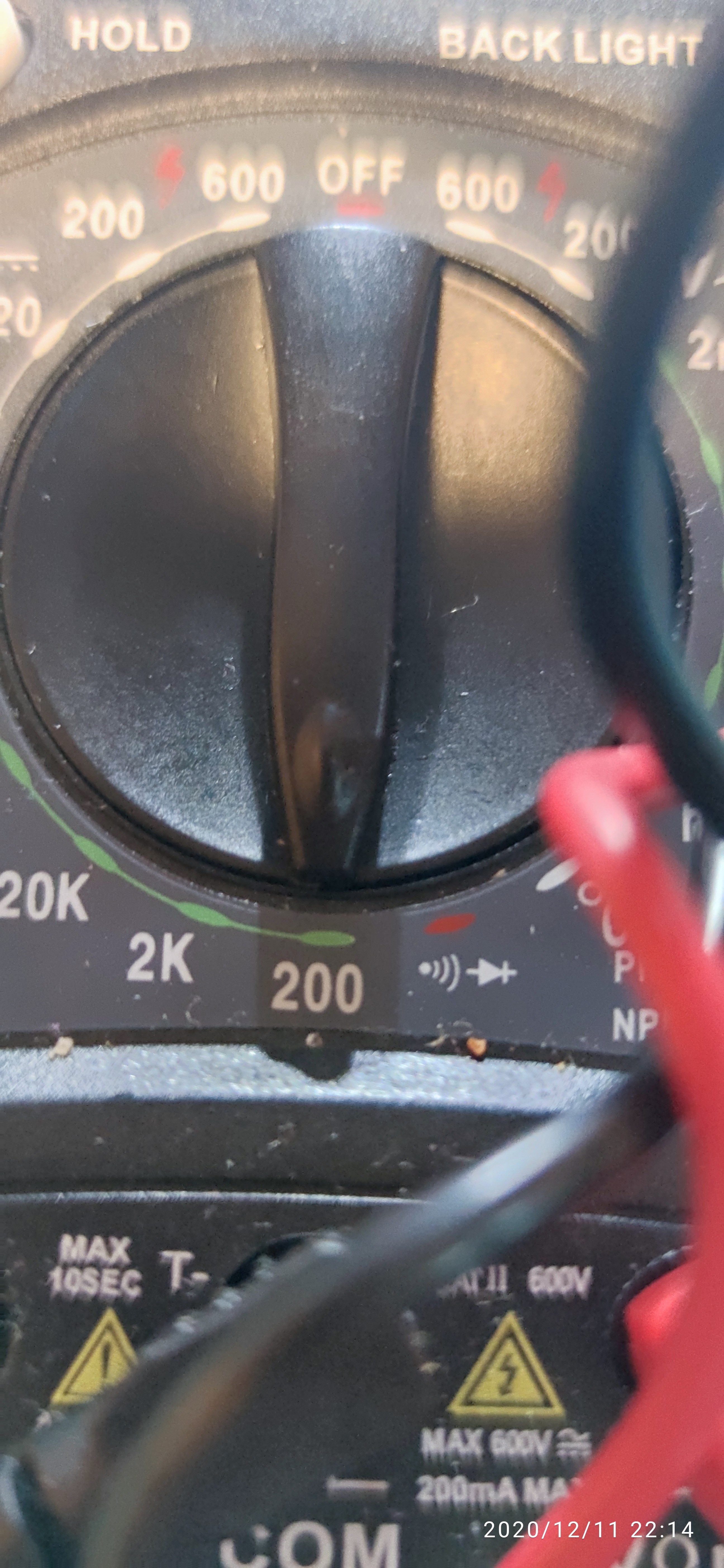
Sorry your measurements make no sense… is this in ohms? is the battery disconnected? make sure your not in continuity mode.
“Blue line is 00.0” 0ohm or OL ??? either way doesn’t make sense, dead short bad but fully open is bad too, need to verify your meter
If you want me to confirm take a picture of your meter in resistance mode
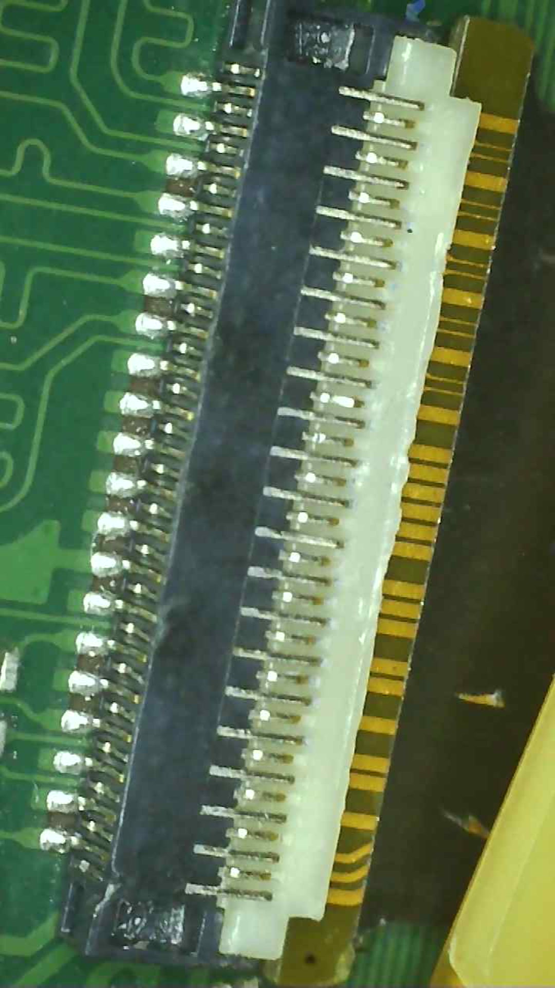
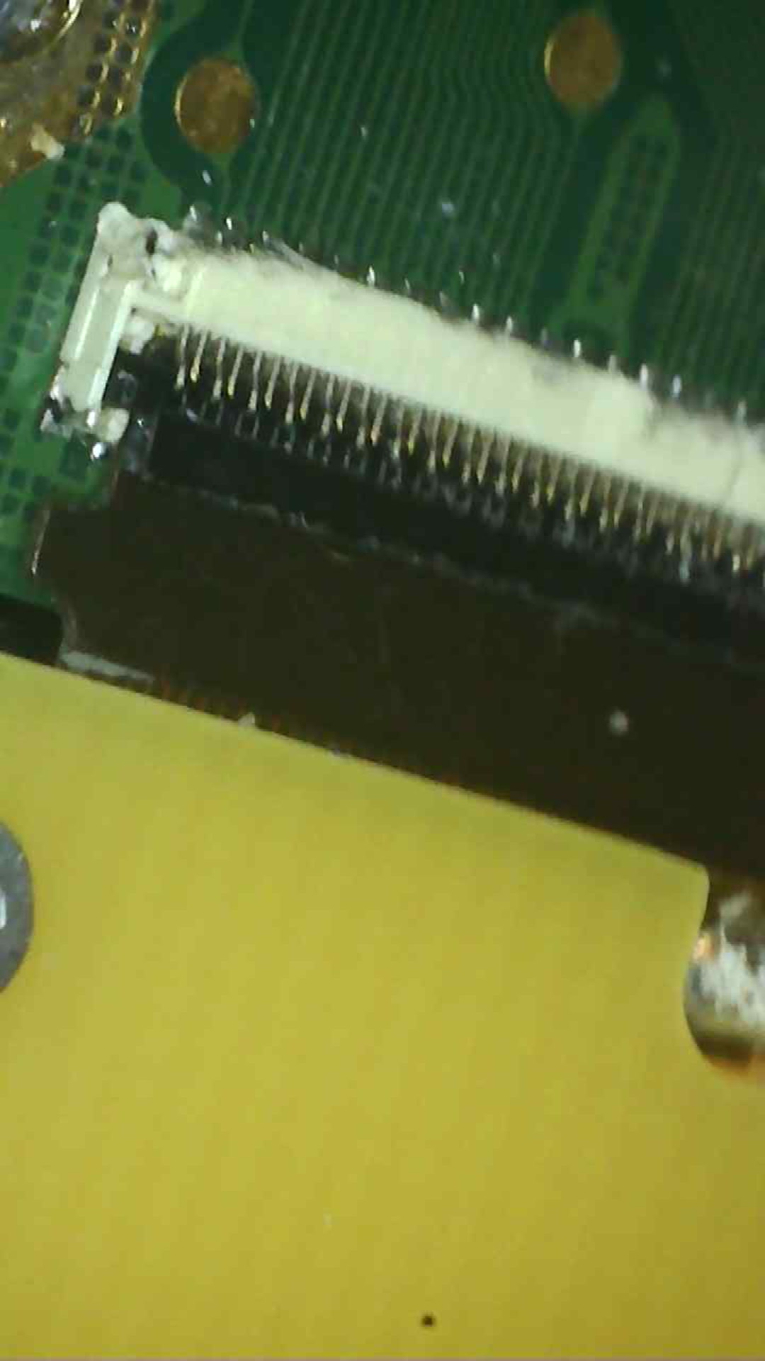
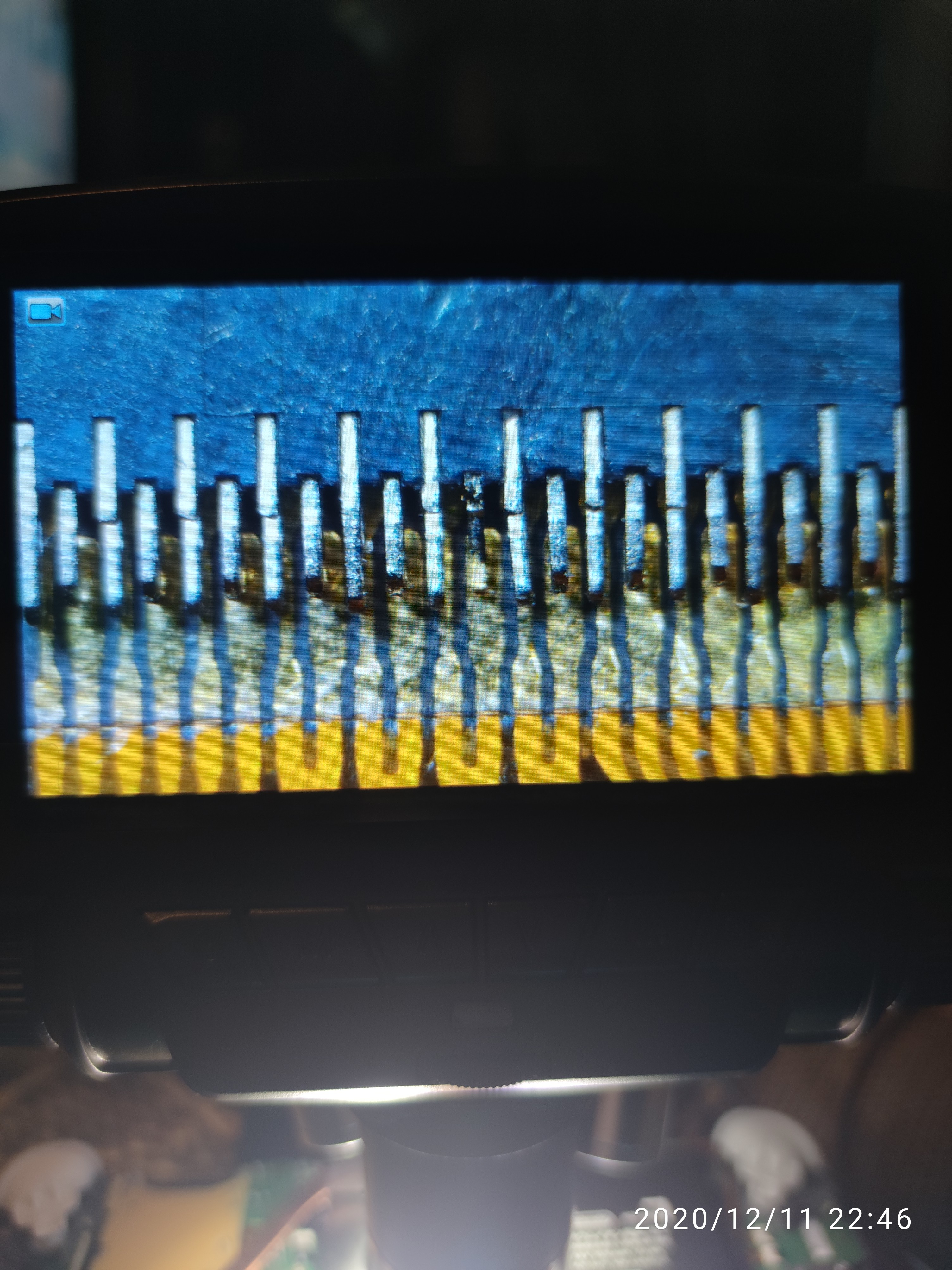
btw 3rd pic of connector - it’s toast and needs changed on first impression, you can see the bent pins - can you photo contact side of this ribbon…i expect damage
Sorry for being such Noob I’m learning this as I go along and more of a hobby than a job unfortunately, it’s on this mode below. The connector is of the digitiser I believe and I’ve got a spare one I can exchange it, il give you the rest of the pics tommorow thank you very much for helping btw
Don’t worry about it, it’s the best way to learn, though i’d reccomend maybe starting on something you don’t care about as much
So you’ve got a manual ranging multimeter. this is a low resistance circuit I’m asking you to measure so what you want to do first is put the dial to the 20K position to start with, second - touch your leads together to check your meter integrity, the meter should read 0.0X ohms (dead short) put your black probe on one of the big copper screw hole pads on the board, it doesn’t matter which one, theyr’e all ground, then put your red probe on one of the inductors (the grey rectangles next to the caps you were trying to measure before) you’ll get a resistance reading, it doesn’t matter which side of the inductor your probe is touching,
now if the number is 0.10 for example then thats 0.10kiloohm … to make this more readable switch your meter to the 200ohm scale and it will show 100ohm for example, which is the sort of values I’m after.
keep your black probe on ground and repeat on all those inductors in that area and log the results, then simply swap and put your red probe on ground and put your black probe on each of the inductors in that area and log the results.
If at any time the meter says OL then simply turn the scale up a notch. though i really would reccommend buying an auto ranging meter, uni-t sells some really good hobbyist meters for virtually nothing and will save any doubt
Hello there, thank you for showing me the ropes and I got the readings over here, hope this will sort out what’s going on with this switch I also took pictures of the LCD connector and the digitiser connector clearly for you, thanks again for your help!
Top right inductor red on inductor 8.11
Black on inductor 0.65
Bottom right inductor red on inductor 0.04
Black on inductor 0.04
Bottom left inductor red on inductor 0.00
Black on inductor 0.00
Top right inductor red on inductor 0.01
Black on inductor 0.01