I’ve got a OLED here that’s stuck on the early stages of first stage boot. No screen, stuck on 0.42A. Current diagnosis as follows:
Unit had evidence of water ingress. Cleaned board in ultrasonic bath. Looks like new.
All rails check out OK. 1v35 missing, but this is known to come on later in boot cycle on Mariko.
I2C Port 0 is high, but has no activity/clock - M92, BQ, Temp and Audio are main items on this port
Fuel cell replaced
EMMC reflowed
Unit is not in RCM mode suggesting that BPMP has not panicked / EMMC visible (?)
Pressing down on CPU and RAM in various configurations doesn’t change anything
Any thoughts on next steps? I’ve avoided removing/replacing BQ and M92 as I’m not convinced they have any faults (USB-C looks great). I will check for discrete alarm/fault lines which I believe are used before I2C is used for comms.
EMMC data lines are burried in board to CPU, so may resort to HWFLY header to test those.
I’ve been following the great guidance from the team at RetroSix (eMMC Booting - RetroSix) and whilst I’m not at a position to access Dat0, I can see the clock and it looks like it’s clearly getting into first stage boot right up to the point where the screen should turn on and the Nintendo logo display. Whilst I can’t confirm the data, the clock pattern looks identical to a working reference Mariko Switch…
I know around that point various discretes are checked - I think M92, BQ and Fuel, so going to focus there.
I would think if you’re having an I2C error on M92, it should still allow for boot but produce the 2100-0001 error, no? IIRC faulty BQ / 17050 definitely produces the black screen of sorrow, but M92 even if not giving ok should still allow for boot to error screen? I had a recent board with a corroded I2C trace on M92, would boot to 2100-0001 error every time but couldn’t progress until the line was repaired.
Be curious to see your results on this one as I’m about to dive into a .48a braindead mariko board this weekend.
Been doing some EMMC activity captures using a DSLogic signal analysis tool and comparing a known working board. I’ve pulled the fuel gauge and can see that boot stops abruptly a little further than the OLED gets to. This would suggest that I should be focusing on the BQ first. I agree that M92 comms failure stops boot post the Nintendo logo, so we can probably ignore M92 at this point of diagnosis.
Some odd timing differences in the time it takes to clock through reading Package1 on the Mariko vs the OLED. It’s possible that damage under the EMMC is preventing full bandwidth reads, which while acceptable early in the boot stage becomes a silent boot failure during Package2 execution.
I could try cutting DAT 1, DAT2 and DAT3 on a gash unit and test the theory…
Did you take any snaps of the board prior to ultrasonic? if so might be worth a look
I haven’'t done a lot of work on OLED’s so this may not apply, but on regular revs the 8316 IC is pretty early in boot stage and a fault here could halt boot.
I suppose If your suspecting the EMMC, the easiest thing to do would just be to pull the IC and either bug wire it and read the data directly or solder the IC onto an original rev switch EMMC module board and read the data off in Hekate or PC… I have no idea if boot0/1 are easily avliable or generatable for OLED models but if they’re not you’d wanna go with the second approach of using Hekate to make the dump so you get these partitions
It’s important to remember that M92 is not the only thing on this serial line/s / bus, there are multiple IC’s and a failure (specifically of the I2C lines of whatever IC) could cause this error. If the serial lines are good but any of these IC’s are bad doesn’t guarantee boot (in the case of M92 sepcifically) as for example, if the M92 was pulling down 3V3PDR or 1V8PDR it would almost certainly prevent booting. Or if the IC/s were incorrectly soldered etc it could also prevent boot Also just to note this error code isn’t exclusive to an I2C issues either, I’ve ran across it a few times where the fault is completely unrelated.
Just to add to this as I was curious as I thought it might be possible to simulate Dat0 and capture data on the other lines (whether or not this is valid I don’t know without looking furrther into this)… I don’t have the inclination to pour over the EMMC protocol nor monitor all the other info which would be needed from scope/LA captures but just for fun I started grilling chatGPT on the subject and well it’s kind of amazing the results… I told it to write a python script running on a rasberry PI, told it to set up the GPIO as inputs for the relavant remaining lines, told it to determine the clock and the byte size and order and then told it to determine the relationship between the clock and the other dat lines, then told it to setup a virtual Dat0 and a buffer for it. all of which it did. Now I can tell this code would still take some pretty hefty manual modifications or more prompting of chatgpt to produce anything truly valid, and you do have keep reminding chatGPT of the code it has already produced in order to keep it on track but if anyones curious or wants a bit of a project this might be worth looking into
I did not. Rookie error. It was light water damage from what I could see. Small bit of corrosion just above the EMMC chip on some bare contacts.
I will investigate the 8316, but suspect it will be different on the OLED.
Agreed. From my notes, the M92, BQ, Fuel, ALC5639 (audio) and TMP451 all sit on the I2C line (Port 0). The issue I’m having is I’m not seeing any clocking, so working on the assumption that the lines are functional, but just aren’t being driven by the Tegra at that point in boot.
On the discrete lines front, the BQ STAT pin is high, with no pulse. BQ IRQ line is high, with no strobe (i.e. no error). On the TMP451m the ALERT pin is low, however looking at a working board, this doesn’t go high until later in the boot process.
I’ll re-run some timings tonight to see when I2C port 0 starts clocking on the boot process and check that against the OLED.
Bit of an update on the whole debug process which has been a fun journey.
I’m pretty certain the OLED is getting stuck at the end of Package1 where it transfers control over to CCPLEX where Package2 is run (I’m not convinced that Package2 is starting on CCPLEX).
I can see activity on I2C Port 4 and it matches what I’m seeing on my Mariko reference unit. This bus contains the PMIC and CPU/GPU bucks and signalling appears to be good and as expected at this stage of boot.
I can confirm that I2C Port 0 does not fire up until Package2, so the lack of activity is expected.
On my reference system, I cut EMMC D3 line and was able to see that Package1 boot fails quite early on. The Switch as expected does some 1 bit negotiation on D0 and then quickly changes to 4-bit mode.
The OLED is getting beyond this point comfortably, so I’m feeling less certain that I have a duff EMMC.
I was considering pulling the EMMC, placing it on an EMMC daughterboard and read it in using my mmcblkNX, however the OLED has Hynix memory which won’t run at 3v3, so I don’t want to risk it. The spec sheet of that brand says 1v9 maximum.
So I’m focusing on the handover to the CCPLEX. Both bucks on the MAX77812 appear to be generating 0v6 and 0v8 as expected.
I’ll try and publish all of my DSLOGIC logic analyser findings at some point. Some useful timing stuff where I’ve been capturing I2C Port 0, Port 4, Backlight enable, EMMC Clock, D0, D3. I’ve also built and aligned the OLED board scans available elsewhere into the same tool found on balika011.hu - I’ll make that available soon.
I don’t have an OLED board atm but doesn’t it have the same 3v3 and 1v8 rails as a standard revision making there way to the EMMC? I imagine the 1V9 Max is in reference to VCCQ or “interface power” line .Though I believe mmcBlkNX outputs 3V3 on both VCC and VCCQ which most EMMC IC’s will tolerate but there are a few modules such as your Hynix brand which will not. You could solder it onto a regular rev EMMC PCB and then dump the contents on an unpatched board via Hekate instead, that way you know for sure VCCQ is not abiove 1V8. Or you can just dead bug wire it and solder them to the switch board, afair Hekate will happily dump even in single bit mode (but will present a warning)
Looking at those board scans, there is a small area of the board which is just a ground plane and and just below it seems to have acess to all data lines, you could grind down in that section to gain acess to dat0 etc though perhaps a bit risky.
I think the trouble with these board revisions is the boot process never seems to be the same as the last, like how Mariko/Lite boards have a completely different core rail sequence as compared to the first revision boards, as well as standby voltages are completely different too. I’m not 100% sure for example if the CPU/GPU rails come up straight away on OLED or if they work more like the standard revision boards and come up later, or if 0.6V and 0.8V is standby voltage and perhaps jumps to 1.2V (for example) later. Can somebody else with an OLED confirm this?
So latest update from my testing is that I pulled the EMMC from the OLED board, mounted it onto a spare daughterboard and read it in with Hekate on an unpatched Switch. I was able to perform the full 64Gb dump and benchmarks appeared to pass fine.
Not sure there is much I can do with this as I don’t have the keyset from the OLED, but it certainly seems to suggest that the EMMC IC is fine.
The EMMC pads on the OLED board look in great condition, so no evidence of water having got under the chip.
I’ll get the DAT0 line wired before I refit the EMMC.
Good to know the data is safe. Might still be worthwhile transferring the data to another known good EMMC on the off chance one of the data lines or similar was bad on the OLED EMMC . It might also be worthwhile taking some readings on the core EMMC lines/pads on the board while the EMMC is off and making sure nothings open or is reading funny.
@jkyoho Do you have an OLED handy atm? It would be worthwhile knowing from a known good what the CPU/GPU buck behaviour is prior to prompting to boot and then following and if the voltage output changes during entering OS etc
ill be taking a few apart this weekend to do some work on. If you have some relevant test points and procedures, just let me know and I can get you readings.
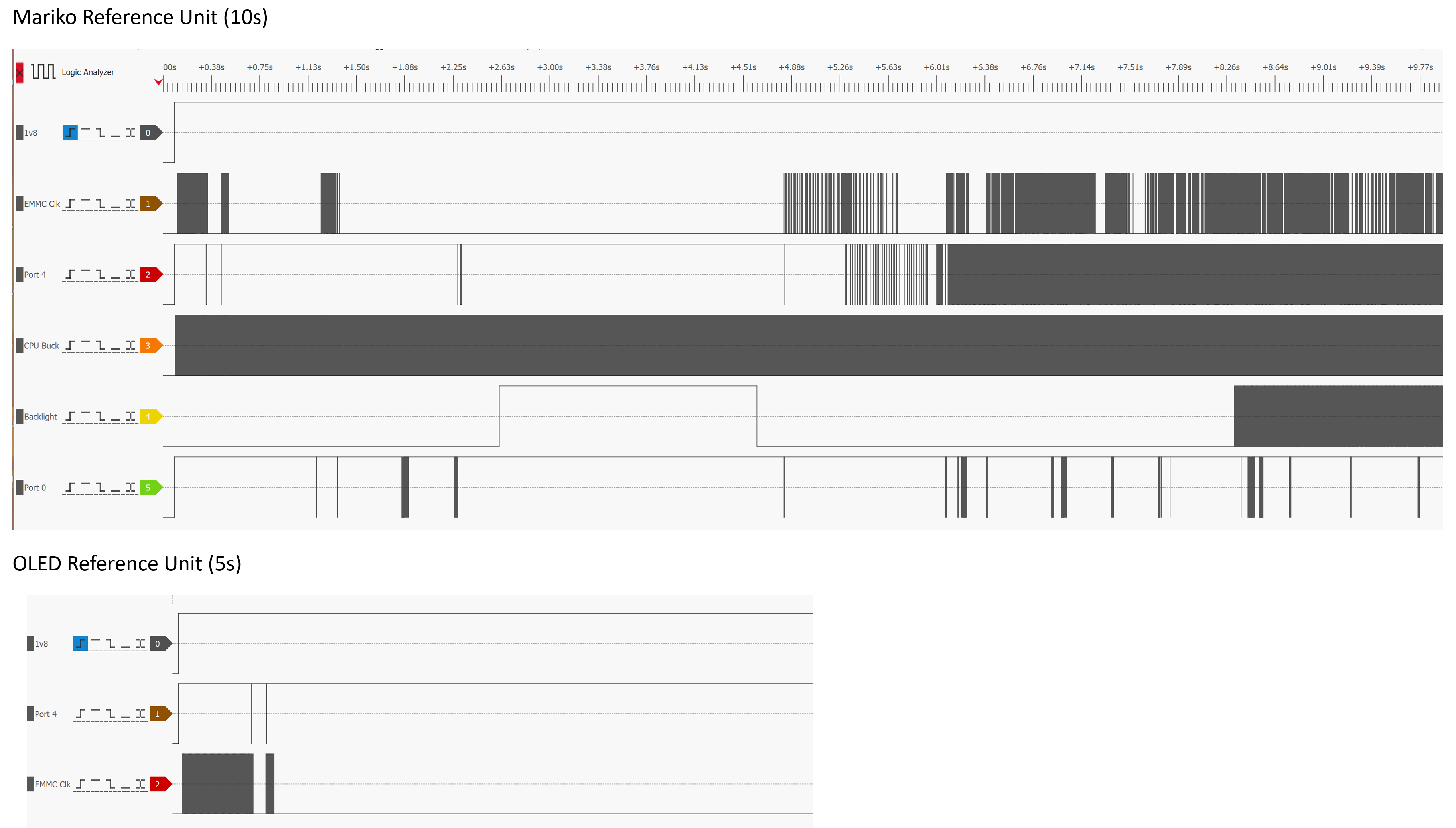
Here are two side-by-side captures. The first is my Mariko reference unit with 10s of boot activity. This uses 1v8 as the trigger and includes EMMC Clk, I2C Port 4 clk, CPU buck, Backlight enable and I2C Port 0 clk.
The second is my OLED with 5s of boot activity showing 1v8 trigger, I2C Port 4 clk and EMMC clk. I didn’t include I2C Port 0 as it comes on later.
To clarify, I2C Port 0 on the OLED has no activity. I suspect boot is failing before this port gets used. Port 4 is used earlier in the boot process to setup PMIC and bucks and appears to be running fine with identical data streams to the reference Mariko board.