No difference was made upon removal the MAX chip to the left of the SOC. Though after I removed the big square MAX IC on the back, the sys rail diode reading now is 105. So it’s gone up but that still seems to low? I think it should be somewhere around 350V.
Sorry, my story to my short at the vsys line was missleading.
It is easier to pull the components, check and test and resolder them one by one. Otherwise you have to memorize where each with its different capacity belongs.
Instead of taking vague diode mode reading which will merely infer the in circuit resistance, instead, measure in resistance to begin with ![]()
Also I’m a bit lost as you mentioned in the first post
which would be normal, but you’ve since said that the caps are now [always] shorted or being dragged down, what changed between then and now?
Bent USB pins can cause a subsequent short on the SYS rail in some cases so that might be worth checking. You can somtimes track the culprit down by putting your meter in resistance and going over the areas of the board where this rails show up and see which area constitutes the lowest reading further narrowing down the potential culprit.
Ok resistance mode, will try that. So before, the caps in question were the 3 around BQ that would give me a -538 diode reading (which at the time I didn’t know what normal) so I removed the MAX IC under the SOC because I know that shorted caps near BQ see sometimes linked to that max chip. So with the PMIC chip (I think that chip is the PMIC chip) removed I started testing for voltages with the battery plugged in as well as with the battery + charger plugged in (which I think is something I shouldn’t have done with that MAX IC removed). I think that’s what perhaps caused the sys rail short because that’s all That changed. Im learning a lot from working on this particular switch :).
It is technically a PMIC, but generally when people are talking about the PMIC on Switch theyr’e reffering to the main PMIC on the otherside of the board, the biggest of the three Max IC’s
All three of these Max IC’s VIN comes from the SYS rail so they all have that in common, so if you don’t measure proper SYS rail voltage at the 2R2 coil you also won’t see it anywhere else
Hmm thinking about it perhaps what caused the change was the probing the board in diode mode while the board had power which may have killed something else and this is a secondary fault… I mean I could be wrong but it’s entirely possible. Perhaps if your resistance readings don’t shed any light then might be worth pulling the BQ IC off again just in case and just keep it off until you find the actual culprit it it isn’t the culprit itself.
best way ![]()
Thank you for the clarification! So with the battery plugged in only, the voltage at the coil matches the voltage of the battery (3.92V), which I assume is what’s supposed to happen? Now with the charger + battery, the voltage at the fuse matches the 5v charger but at the coil it’s 2.08V. Not sure of what to take from that. Also, are you suggesting that I use resistance mode and go around the sys rail looking for a low resistance value compared to the rest of the rail?
Yeah, you can think of the SYS rail kind of like regulated battery voltage but independent of one another.
Strange, maybe it’s pointing to USB or USB related circuitry (m92 etc) issues.
Correct. So if the SYS rail is shorted to ground, and let’s say it’s a 10 ohm short to ground (just for example) measured at the 2R2 coil, then you might go over to SYS TP beside the main PMIC and measure the resistance to ground there also (making sure to keep the same probe polarity as you did at the 2R2 coil), it might measure 9.98 ohms (again just for example) as it’s a lower reading your “warmer”, then you might measure this rail at the other two max IC’s and let’s say they measure 10.33ohm - this is higher, so your “colder” then say you measure the SYS rail at the 8316 IC and it measure 8.7ohm bingo, most likely candidate. Just checkout Calvins diagram for most of the places where the SYS rail shows up. Hope that makes sense.
1 Like
By polarity I assume you’re referring to the 200M, 200K, 20K, 2000, ETC modes on the multimeter? I set the DMM to 20kohms and at all of the sys rail components I get 0.10, there doesn’t seem to be any deviation unfortunately.
No, as in your probe poarity, black probe on ground and red probe at the point of interest
So as your getting 0.10 on the meter, to make it more readable and more accurate adjust the range lower, keep going until it’s at it’s most readable but still within range (this might be 200ohm on your meter… I don’t know)
There will be, hopefuly once you’ve adjusted your range it will improve accuracy, you should see minute devation on this rail across the board. If you still don’t then it’s probably your meter at fault - UT61E is my reccomendation… not need to faff about with ranges after that either.
Does the LCD driver (the BGA IC that’s right next to the LCD FPC connector) reside on the sys rail? The cap that sits on the sys rail makes me think yes. If so, good, because there is deviation in terms of resistance compared to the rest of the components. On the other components I’m reading 107 where as at that sys cap next to the LCD driver is getting 106.2-106.7. Should I remove that cap as well as the IC?
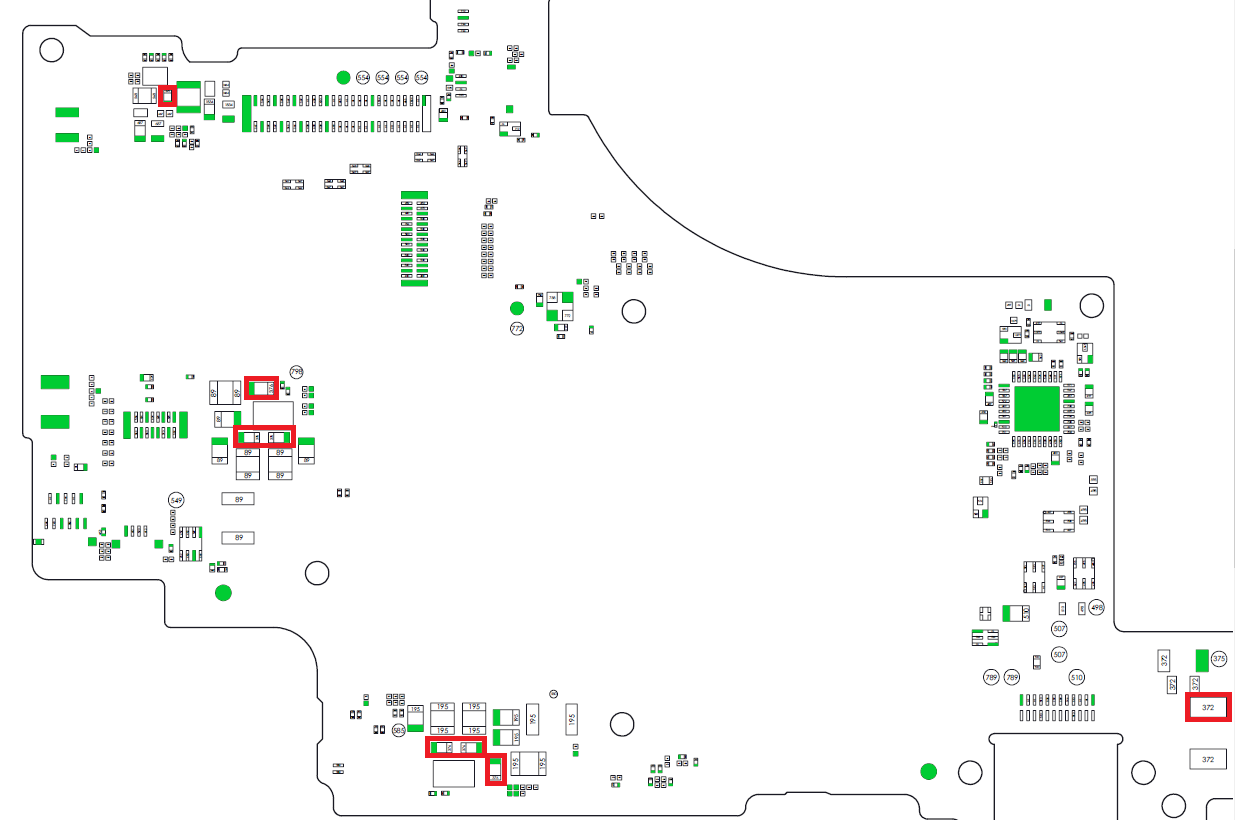
Top left cap.
Correct, it’s VIN is SYS afair
So is this 107 cats or 107 dogs, or is it $107 ? ![]() without knowing what range your meters in this could mean anything, I assume your in the 200 ohm scale and this is 107 Ω
without knowing what range your meters in this could mean anything, I assume your in the 200 ohm scale and this is 107 Ω ![]() (?)
(?)
If that’s the lowest reading at any of the SYS rail location/s, including the other side of the board then it may be a good idea.
Before that though and given this is a “high” short to ground, it might be worthwhile checking a few other rails, as this isn’t a direct short to ground it can often imply it’s a secondary fault, with the primary fault which has SYS in common in some way (a chip which is connected to SYS and another independent rail for example) which is in turn dragging SYS down as a byproduct.
So, I would check you 3V3PDR - this can be found a few places, pin 6 of the M92 IC or the largest cap next to the P13 IC, just place black probe on ground and red at the point of interest and let me know the resistance reading, same as before, start with your meter range set high and adjust downward until the reading is most readable. I’d also do the same on your 1V8PDR - I’ve covered it’s location a bunch here on the forum so I’ll let you find that ![]()
OOPS I should’ve clarified haha, yes you’re right 200ohm scale was used to take these measurements.
On 3V3PDR (using the big cap next to PI3) I get 165kohms using the 200k ohm scale. PIN 6 of M9 gives me 167kohms at the same 200k setting.
On 1V8PDR (using the cap under M9 as well as the 1V8PDR resistor near BQ) I get 298ohms using the 2000 ohm setting.
Thank you so much for helping, I’m learning quite a lot!
Haha no worries :![]()
That’s good ![]()
Oh dear, that’s no good, Main PMIC would be my first thought at this point. You can apply the same method as you were with the SYS rail and dot around the board and see which area of the board on your 1V8PDR constitutes the lowest reading to get a better idead… trouble is, 1V8PDR show up pretty much everywhere so it could take a lot of time.
What was the resistance to ground at thte SYS testpoint next to the main PMIIC? still 107 ohms or lower?
No worries, glad to hear it ![]()
Yes the sys test point is still 107. How would I determine what components are on the 1V8PDR rail? Is there a chart I can follow? I’m currently scrubbing through the forum to find something.
Hmm ![]() so afair the 8316 IC doesn’t have a direct connection to 1V8PDR… so it’s unlikely to be that at fault… but if I remember right, the LCD connector does have direct connection to 1V8PDR and the LCD connector is also being supplied a couple of rails by the 8316 IC, so if there was a bent pin in the LCD connection if could cause these fault symptoms. I would really hone in here and take a close look inside the connnector and check, if you don’t have a microscope then your phone camera is probably your best bet in decent lighting.
so afair the 8316 IC doesn’t have a direct connection to 1V8PDR… so it’s unlikely to be that at fault… but if I remember right, the LCD connector does have direct connection to 1V8PDR and the LCD connector is also being supplied a couple of rails by the 8316 IC, so if there was a bent pin in the LCD connection if could cause these fault symptoms. I would really hone in here and take a close look inside the connnector and check, if you don’t have a microscope then your phone camera is probably your best bet in decent lighting.
Also, it will probably be fine but just to rule it out, it might also be worth measuring the resistance to ground at the USB fuse too.
Sorry I haven’t made a diagram and I don’t think anyone else has posted one but I and others have covered it’s various locations scattered across several topics… sorry, you tend to just know off by heart after a while of doing it. In your case you can just look out for an approximate reading of 298ohms if your unsure.
The pins are in immaculate condition. No bends there.
As far as the fuse resistance with the 200M (couldn’t go lower) ohm setting selected I get 1.56M ohms on both sides with black probe on ground. I do get continuity through the fuse.
The inductor above the PMIC, to the right, matches the other 1V8 components resistances so I assume that inductor is apart of the 1V8PDR rail. Oddly enough, the inductor just to the left of it doesn’t even give off a DMM value at the 200 ohm setting.
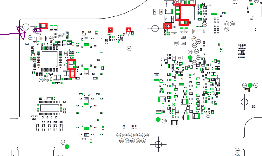
Also, is this cap circled with purple, top left, linked to 1V8?
I see, shame
Right, this is the output inductor for this whole rail
That ones 1V35 and will typically fluctuate or measure in the high megs, wouldn’t worry about it. While your there, what resistance to ground do you measure on the other three inductors by the PMIC (two of which are the same and will measure as such) ?
Resistor, and yeah. left side is connected
On the 2 inductors to the left of the PMIC, I get 27.6 ohms with the 200ohm setting selected. As for the 1 on the bottom I get 136.8 ohms with the 200ohm setting selected.
Hmm this is a touch low if this is an original rev board, but that could just be because the SYS rail being low is skewing it somewhat.
![]() these ones are always a pain, just so not to get your hopes up, usually when it’s SYS and your 1V8PDR together, it’s the SoC a lot of the time
these ones are always a pain, just so not to get your hopes up, usually when it’s SYS and your 1V8PDR together, it’s the SoC a lot of the time ![]() but I’d press on with checking resistance around the board on your 1V8PDR and see if you can gain a consensus between that and your SYS rail and see if it’s something which they both have in common.
but I’d press on with checking resistance around the board on your 1V8PDR and see if you can gain a consensus between that and your SYS rail and see if it’s something which they both have in common.
Failing that, you could pull the 8316 IC and/or nearby cap as that was consituting the lowest SYS measurment but tbh I can’t see how it’d be that with the high short on 1V8 too and this not have having a direct connection to this rail… so it might just wind up making more work for yourself if you were to ever get it working.
I think I got excited and jumped the gun when diagnosing the initial issue, which lead to more faults to be produced. The screen and backplate are in fantastic condition so I don’t mind using this board for parts. My DC power supply just came in so I supposed I should at least try to inject voltage and see if anything gets hot enough? I’ve never used one before so do I just put one clip on ground and the other red clip onto 1V8 and SYS?