Yeah it’s worth a try, though you’d wanna play it safe and set the voltage no higher than 1.2V, which means no more than about 0.10W of heat on your SYS rail short which is going to make it tough to find, not sure IPA will tell you much, Acetone maybe, freezespray might be better
negative lead to ground (typically black) and positive (typically red) onto the SYS or 1V8, always make sure your polarity (lead direction) is correct prior to enabling the PSU output, if your unsure double check everything with your meter in continuity first.
One thing to watch out for, the leads that are typically supplied with bench PSUs are quite often junk, I would make up your own leads - if they’re croc clips I’d remove their wire and solder your own heavy gauge wire into them instead. I’d also suggest soldering heavy gauge fly leads up to the board for you to clip onto, don’t use a probe to supply power like I’ve seen some youtube idio… erm “pros” do
They’re alligator clips. So you suggest, in general, I solder heavy gauge wire to whatever component I’d like to test? And attach those clips to those and inject voltage that way?
General Question: How do I know the safe amount voltage is being injected? Is it dependent on the type of rail?
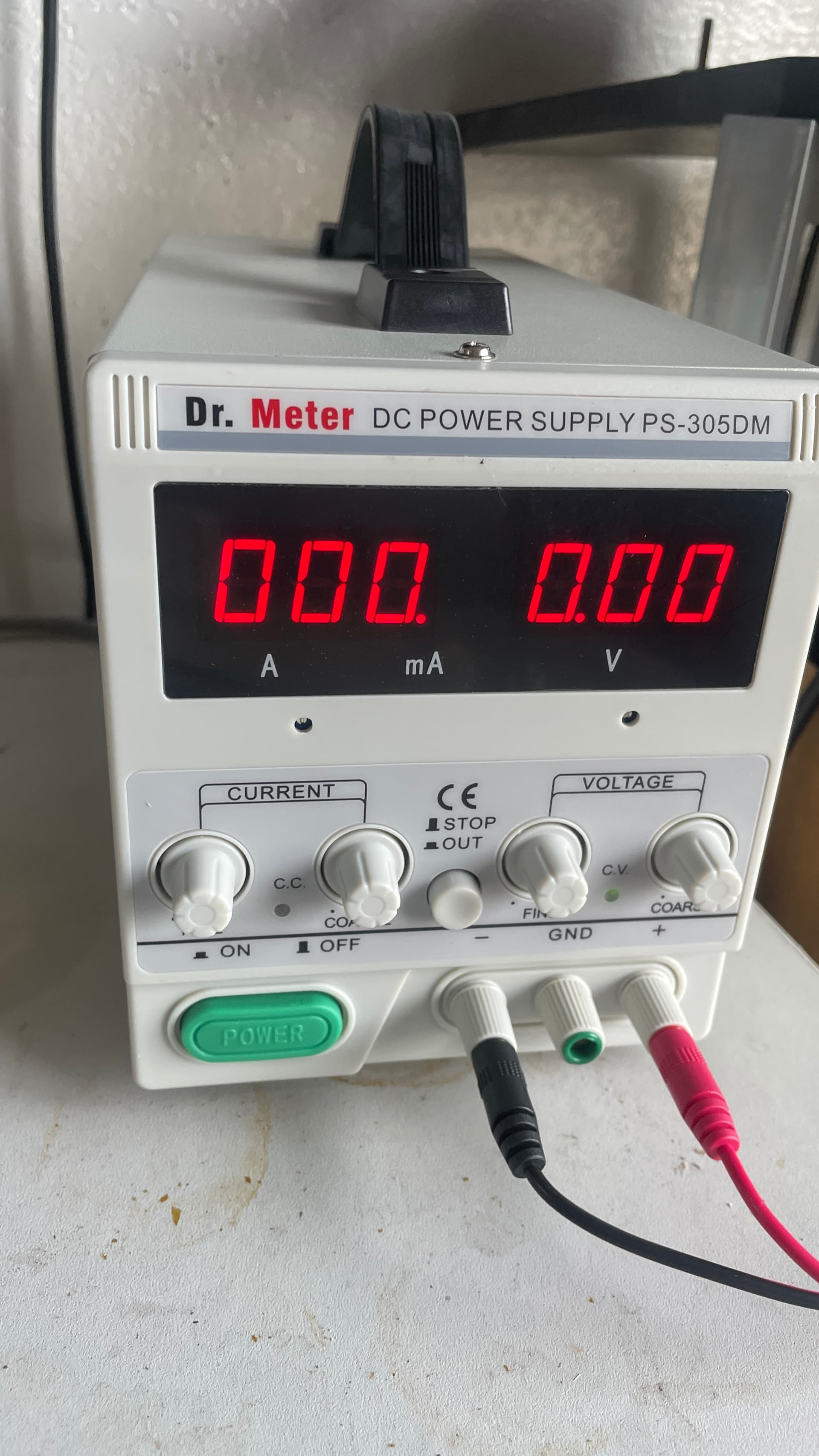
Would you mind sending a picture of how you’ve got your “probes” setup?
Right so if you remove the shrouds of the clips, you’ll probably find either bad soldering of the wires here, or no soldering at all of the wires so you just just want to solder in your own chunky wires here to minimize the losses.
Right, to whatever you going to be attaching your bench PSU up to. keep these fly leads as short as possible and as heavy gauge as will feasibly fit (and fit without causing damage due to strain etc when flexing) - it’s just safer, you’ll see some people in videos connecting their PSU up to multimeter probes instead but it’s a bad idea for so many reasons, so avoid that
In this case, a fault on your 1V8PDR and SYS rail, they both have something in common with the main PMIC, which generates much lower voltages, and in the event that one of these higher voltage rails was shorted to a lower one - or could devlop into a short if allowed to, then absolute max would be 1.2V (and that’s pushing it, but not much choice)
In general, if you don’t know much about the board your working on, 0.8 to 1.2V is a safe bet.
If say for example you were working on a device where the lowest voltage rail present on the board is 5V and you know that for a fact, then you could supply 5V. Or lets say you have a board which has a 12V rail and a 5V rail, there’s a fault on the 12V rail, you could connect your PSU up to the 12V rail, if you know for sure that the 12V rail circuitry is completely independent from the 5V rail circuitry and they share nothing in common, you could go straight to supplying 12V in that case. Hope that makes sense.
Do you mean my PSU leads? they’re nothing special, just some heavy gauge flexible test hookup wire with some decent banana jacks soldered one end and some decent croc/aliigator clips I found on ebay soldered onto the other end
I set the voltage to 1.0V and connected a wire to the sys rail (big coil) and saw an amp draw (which I believe implies a short somehow?). It was the LCD driver ic that was getting hot. Removed it but sys rail resistance reading was still too low. Was still cool to see :).
Now it’s connected to 1V8PDR at 1.1V and there’s an amp draw of 214 (I’m assuming it’s mA because 214 amps seems absurdly high?) and I’m having trouble locating the culprit.
You’d get current draw even under normal circumstances. In the case of a fault condition, a short for example, the current draw is directly proportional to the severity of the short - or put another way, the lower the short circuit resistance is, the higher the current draw (see ohms law) which is why “high” shorts such as this are such a pain, less current draw creates less heat which in turn makes culprits harder to find
Interesting. good to know your previous measurments pointed pretty clearly to the thing that was going to produce the most heat. Out of interest though, how much did the in circuit resistance change on this rail after pulling the IC?
I guess. I take it this is one of those mini switchmode PSUs with no unit of measure on the display or at the least just a decimal place? I hate these things
Ah I see. So say there was a flat short to ground, the current draw would most likely be high due to 0 resistance, leading to a perceivable thermal signature?
To answer your question, in circuit resistance changed very minutely. From I believe 107ohms to 112.4 ohms.
Yeah kind of, nothing can ever truly be zero in terms of resistance
I see, provided you maintained the same probe polarity (black probe on ground) during these measurements, the difference is enough to have me believe that this was at fault too in some way.
You could also remove the 2R2 coil and see on which of the two pads your SYS short remains on, I expect it will stay on the output side as I can’t see how the other end would be dragging down your 1V8 rail mind… that is unless by some chance you have to independent fault on each rail not relating to one another (unlikely I think)
If it ultimately comes down to the point where you can’t figure this out and have exhausted all other possiblities, you could pull the PMIC and the CPU and GPU regs (the other two max IC’s) then up your SYS rail voltage to approx 4Vno your PSU which elminates a lot of the risks we were talkng about earlier… if I remember correctly I don’t think the SoC has a line to the SYS rail
About your PSU, I would have thought the decimal place would move at the very least to give an indication of it’s unit?
I’m not sure which pad is the output/input but the high short is present on the top pad, the pad closest to M9.
With all MAX ICs removed, current draw was 031. A at 3.98V. Nothing is getting noticeably warm unfortunately.
Anyways, I’m going to just use this board as a donor, I’ve got 3 other switches coming in today that I need to shift my attention to. Believe it or not, I regularly work on switches but the fix is always simple. It’s usually the case of a shorted M9 or something basic like that. Learned a lot from working on this one though so I’d like to wrap up my thoughts on things I’ve learned so as to retain all of this information. Also perhaps receive some answers on things I’m a bit confused about:
Don’t test in diode mode with battery attached (or presumably any vessel of a voltage source such as a charger). I believe this is due to voltage from the battery interfering with the way voltage is used during diode mode?
2.Different voltage rails on a device may be independent or linked together to some capacity. Now, in order for multiple voltage rails to be considered linked, would a component have to have multiple VINs from different rails? So the PMIC has voltage input from I think the majority of all the voltage rails on the switch therefore all of the rails that converge at this IC are linked?
A method for short finding is to identify which rail the short is occuring on and then test other components on said rail in resistance mode. The component with the most deviation in terms of resistance is the component that should be further investigated. Now I don’t really understand how this works. So lets use this topic as an example. A short on SYS was present so I went around testing the components on SYS looking for deviated resistance readings. What I don’t understand is what would cause that deviation? Does a faulty component’s behavior just produce lower resistance readings compared to non faulty?
I suppose this question is linked to point 2 but In terms of voltage rails, is their a hierarchy in which the board will utilize the voltage? So does the PMIC only have the sys rail as its VIN and not the multiple VINs that I said it did above? Does it then take that single VIN and output into the various rails?
Thank you so much for all the help and information. Over the last 7 or so months I’ve referred to many of your posts, indirectly receiving help and learning. It’s greatly appreciated and I look forward to passing on what I’ve learned from you to others who are just starting out
Correct, this also includes reistance mode too. Basically, the only mode your meter should be on when the device has power in some form or fashion is voltage - there are a couple of others such as Hz which is fine but for the most part just remember “only on voltage mode when powered”
Yeah kindof, if the board is outputting say 4V and you probe it with with your meter in diode mode in reverse polarity (red probe on ground) you exposing your meter (which remember is in reverse polarity) to a positive voltage, so at best you’ll get a duff measurment and at worse you could damage your meter (though tbh, most meters these will tolerate this abuse) the opposite is true also (and this largely depends on the forward voltage at your meter probes and/or the current limit) but you could damage the board and it’s components in some way - all this is true for resistance mode readings too.
When I mentioned inferring earlier, what I meant was, diode mode is for testing diodes, so when people say “let’s check for a short” and then " I’ll put my meter in diode mode" it’s a pretty backwards way of doing it… I wouldn’t for example say, “lets check for a short” and then “lets measure the voltage drop on the said rail” as, one, it would take longer and wouldn’t be as clear and to it’s inference. Hope that makes sense. In circuit reverse polaity Diode mode was popularised by Rossmann and the like years ago and has persisted to this day (and I do like the guy) the reasoning for using it back then was meters (and I’m focusing on auto ranging meters here) with fluke being the worst offender were painfully slow to automatically cycle through the ranges, in contrast, diode mode could provide a “inferred” reading significantly quicker, and typically faster still when probing reverse polarity than their resistance mode/s. Similarly, manual ranging meters can bypass the owners knowledge of understanding resistance ranges on their meters which is simpler for beginners… but, all of this comes at the expense of overall resolution and accuracy, which is why I say it’s vague, diode mode reading to me are only good for a rough pass or fail not much inbetween and besides, things have changed quite a bit over the years, most auto ranging meters these days will auto range as quick or quicker than their diode mode counterpart completely nullifying this issue and which is why it always leaves me scratching my head why the “pros” still bother with this mode…
I wouldn’t say linked, I’d use the term “in common”, let’s take the main PMIC as an example (bear in mind I don’t have the datasheet for this IC so I’m just guessing) it’s primary VIN is SYS at approx 4V, it takes that 4V and converts it into 1V8, then I imagine it takes that 1V8 which was initially derived from SYS and converts that 1V8 into 1V35, then I imagine it takes that 1V35 and converts…and so on and so forth with the other various rails the PMIC creates. So you can imagine if there is a fault one of any of those rails one could affect the other. This in turn gives you clues, for example, if those 1V35 and 1V8 rails were both simultaiously shorted to ground, you could say with a high degree of confidence it’s either the PMIC at fault or the SoC, likewise with faults on the other rails.
In the case of the PMIC, it has atleast two input, prrimary VIN is SYS, and 3V3PDR - which maybe for general I/O or maybe a power good. All those other rails I mentioned above are created by this IC and are outputs.
Correct but, the most devation in resistance relative to ground going lower (short getting “worse”)
I think what’s making this harder for you to understand is that this isn’t a dead short. So lets say your SYS rail was a dead short to ground, lets say 0.8ohm, now you go round the board in the same manner as you mentioned looking for the biggest offender of downward devation, you find the cap next to the 8316 IC on this rail and it measures 0.6 ohm and this is by far the “worst” reading you’ve found on this shorted rail across the board. So you opt to pull the IC, it clears the dead short as the IC was faulty and your now reading 1.2Kohms relative to ground, the chip in this (example) case was dragging this rail down but this rail is still reading somewhat on the low side - perhaps whatever caused the fault to begin with damaged some other IC/component on the board, we know there is multiple components which have a direct connection or something in common with this rail, so you could again apply the same methodology and repeat the process. I hope that makes this process more understandable and clearer not everything fails in the same manner, so it’s not as black and white as some people make it seem
With the deviating short readings, the thing to remember is that the wires themselves have resistance. So if there is a long trace between when your probe is, and where the short is being created you will also be measuring the resistance in that long trace, which makes the reading higher. (Or at least, that’s how I see it, there may be other factors at play…)