Hello Guys,
Could you please give me a reliable source for Switch replacement batteries. I ordered now 2 from China which looks like the original and the seller was with quite good rating but the batteries capacity is way below the rated. Even after 2 full charging cycles they are discharging 20% in stand by mode during a night. They should not discharge more than a few percent.
Thanks.
Test the batteries capacity externally, I use a standard Li-ion/Li-Po battery charger which has this feature.
As it’s possible there is a fault on the board causing the excess draw
Thanks. Ok, I will create a cable with a connector to hook it up to my capacity tester. I will charge it up fully and discharge it with 750mA. I think it should be good.
I can also see most probably a shunt resistor behind the battery connector on the other side of the board. I will try to measure voltage drop to check the current draw on it in standby mode and compare it with an other switch as a second option.
I could measure 4000mAh capacity with my tester so the battery is fine. Finding the reason of excess current draw could be challanging because it is not extreme just slightly higher than usual. I would not expect overheated components because of this. I can imagine a bad capacitor (not fully) for example. Do you have any idea how to start?
Yeah, check your primary and critical rails so it may help in narrowing it down. Check resistance relative to ground at the following locations - On the inductors surrounding the main Max PMIC on the rear of the board, check resistance to ground on 3V3PDR (can be found at pin 6 of M9 IC), check SYS (one side of the large inductor next to BQ) then finally across battery pos & neg connector on the board. If any of these rails show a skewed reading compared to a known good then it’s likely something on that rail causing the isuues.
I will say this is more commonly down to two things, either liquid/corrosion damage on the board (under or around IC’s) or down to poor rework (most commonly M9, BQ, P13) as a result of stray solder or even bridged pins/pads.
Might also be worth checking none of the connectors are scorched or charred.
1 Like
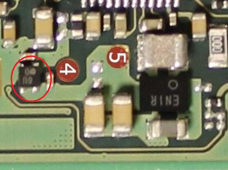
Thanks a lot for the detailed help. I can measure a huge deviation at the capacitor which is next to M92 on pin6 and also goes to P13USB. The resistance is 180 Ohm even if I remove both the M92 and P13USB. The voltages are all ok but for sure this low resistance will result in a higher current draw. What could cause this?
3V3PDR is supplied by the ENXX IC below the realtek IC but there is a few things on this rail, try removing the EMMC and see if your reading improves.
I think the WIFI is also on this rail off the top of my head.
Also it’s probably best not to power on this switch while this high short remains, less you damage a component on the board or potentially even corrupt the EMMC data
Removing the EMMC did not change anything. Shall I try to remove the ENXX IC?
Hmm I’ll have a think on this and get back to you as i have to go over my documentation.
Can you give me a bit of history of the board, such as initial fault, what was repaired/replaced etc?
Yes, for sure. I really appreciate your help. It was not working at all, than I replaced P13USB and than everything works OK now, except this higher current draw. It drains ca 40% a day in stanby mode.
Thinking about it, it’s possible the 3V3PDR can be isolated from the rest of the board by removing the diode next to it… this is from memory mind you and i could be wrong.
So if your revision of board has this presumed diode (4-pin) present in the vicinity then you can try removing it and see if the high short clears at pin 6 of M9, if it does then ENXX IC is responsible in some way.
I assume you mean a 4pin IC with XM D on it. It looks like it is on the same rail like ENXX.
Am I correct?
Markings will be different board to board most likely.
Yes, this is what I meant. I will remove. Just a second.
Still 170Ohm at those caps
Hmm likely not the ENXX IC at fault then. Tilt the board and inspect the balls below WIFI IC, check the caps surrounding it too… in the handful of times I’ve ever encountered a bad cap on a switch it was the cap on this rail surrounding WIFI IC.(from memory anyway)
Check to see if the realtek IC is on this same rail, if it is (i forget) then take a close look at the components surrounding it if they all look good then you could pull this IC… though I’ve never had one fail or have a short in this manner.
Thanks a lot. I will look around and come back later on. Thank you for the help.
This is super annoying that it works basically but there is some small fault 
Wifi balls look OK. Removed also the Realtek audio IC, still the same. I have the feeling that I will never find this short…
afaict Realtek IC isn’t directly connected to this rail (sorry i forgot)
Did you notice any other skewed readings on your other rails earlier?
If not then this is going to be a hard one to track down as the current draw on this high short will be too low to detect it with heat.
There are so many things connected to this rail, for example mosfets on the rear of the board, other main IC’s, the main PMIC etc etc. If the culprit is a capacitor and provided this rail is definitely isolated from all other critical rails i mentioned earlier, then you can connect a bench PSU up to 3V3PDR externally, set your PSU up to supply 3V with a current limit of 500mA (in case soemthing changes) and submerge the board into a tub of IPA, if it’s a failed cap (99% are cracked in some way) then you will see the bubles coming off it.
Failing that, you’ll have to use a milliohm meter and go round the board and try to find the area on this rail which constitues the lowest reading, once you’ve got it you can start pulling components in this immediate area to confirm.
Another way is to use the mV mode of your meter… provided it has the resolution.
And another way is to set your hot air to 100C, connect some fly leads upto the offending short with your meter connected and then hover over certain areas and see which area constitutes the biggest change in ressistance to ground when heat is applied for a few seconds IE: relieving or closing the short as a result of the heat… though i will say this method is a lot less accurate and heat will affect the readings regardless of what area you hovering your hot air, you have to look at the rate of change.
some sort of short sniffer device might be ideal in this scenario… though i’ve never used one and can’t vouch for how effective they are… they might be as useless as a thermal cam for all i know.