Also, If you want you can provide high res photos of the board front and back and i’ll take a look just in case you’ve missed something
Many many thanks for your detailed guide again. I really very appreciate it.
Other rails looks OK to me.
Sorry my english is not perfect so I just want to make sure I did not misunderstood anything regarding the following line You wrote:
Does this mean that this 3,3V rail is independent from other critical rails anyway and I can just inject voltage with my PSU or do I have to isolate these rails myself ?
At first I will try this trick later on the heating trick (last time with this second one I could find the bad capacitor on a Blue Yeti Microphone)
I will also make some pictures with my microscope and upload them.
Thank you once again. I will come back soon.
It is ordinarily, but some faults and failures can cause some rails to merge, this is something you’ll have to check for by checking resistance from one rail to the next, I don’t think this is a problem in your case as your console wouldn’t have booted up previously and 3V3PDR would have been present… but it’s worth checking just in case, last thing you wanna do is inadvertently put 3V3 on one of you 1VX rails.
You can provided the rail is isolated in your case. Be sure to not have the battery or USB power connected while applying power externally
I tried the Voltage injection + IPA bath trick. It did not work. No bubbles, no areas where the IPA evaporated faster  Ok, which is true that with 3,3V the rail is only taking ca 80mA which means less than 0,3W which is quite low. Afterwards I tried to heat the board with my hot air station while the PSU connected and I was looking at the current draw. No change at all. My feeling is that it is not a bad capacitor. Maybe it is the ENXX chip? I think I am gonna try to remove it, I have nothing to loose.
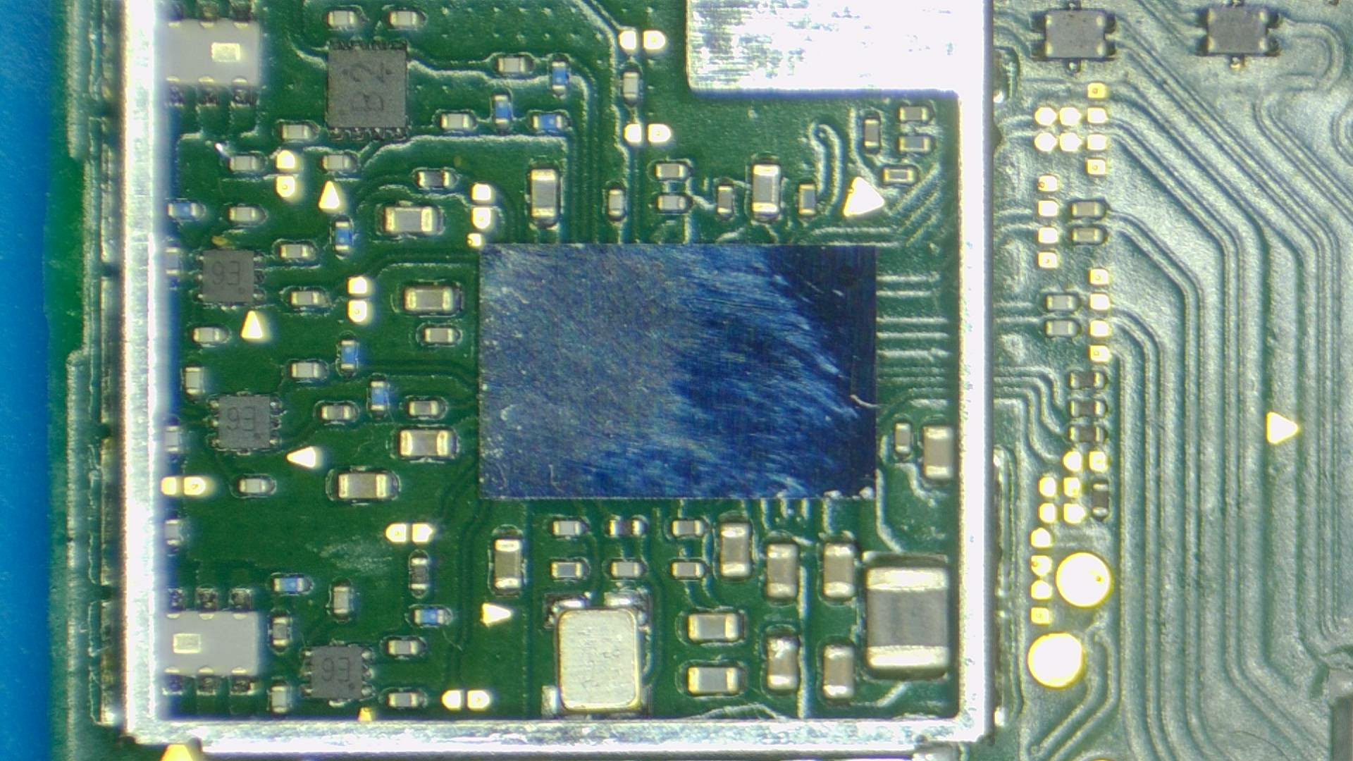
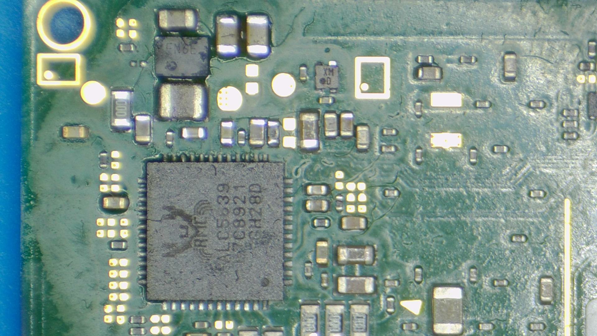
Some pictures attached from the board.
or?
It’s not a good idea to use this trick while power is being supplied, heat will alter any and all rails it comes into contact with due to thermal expansion and contraction, doing so can cause other issues, this trick should be reserved for use with a multimeter monitoring resistance only.
Really don’t think so given your previous tests, very unlikely at this point.
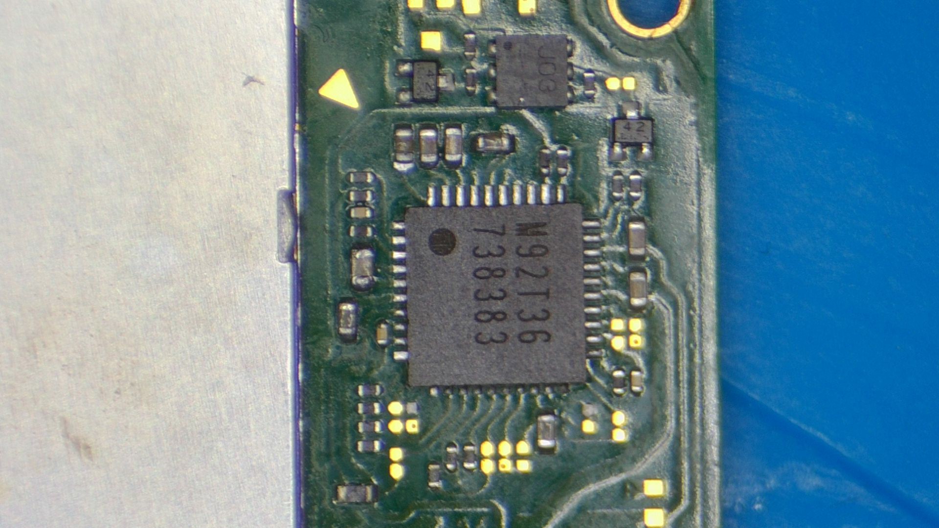
Maybe it’s just a trick of the camera, but your M9 IC doesn’t look 100% centered, even if it’s not, it’s likely not your issue given you removed it earlier and had the same readings on 3V3PDR.
The capacitor connected to pin 5 of M9 IC potentially doesn’t look to healthy, out of interest whats the resistance when measuring across pin 5 and pin 6
I will try without the PSU than with multimeter in ohms mode.
On pin 5 of M92 I have 160kOhm on pin 6 the same 170ohm because this goes also to the P13USB and that is basically the same reading like on the ENXX 3,3V rail. And yes I removed both M92 and also the cap whit the low reading next to it.
Sorry i should clarify, one probe on pin5 and one probe on pin 6
Oh sorry, my bad. It is also 160kOhm.
But becuase pin 6 is close to ground I would expect this value.
On a donor board I have ca 1Mohm between 5 and 6. And in the Mohm range between ground and pin 6.
This reading is correct (on pin 5) as far as i remember, this reading can bounce around and read in the Megs when enabling a junction (probe hitting something else)
Now I removed both M92 and P13USB once again + the caps next to them. Still the same 170Ohm. I am starting to loose hope
If you buzz out in continuity on the rear of the board the various fets and other miscellaneous components on this rail, you can then narrow down a potential culprit by seeing which has the lowest reading relative to ground (there is a lot)
I will say it’s not uncommon in situations like this that i pull everything which is on the respective rail off the board in order to determine the fault… and sometimes you don’t find the culprit.
Sorry, i wish i could be of more help
btw when you were booted up earlier was WiFi and BT working fine?
1 Like
I will buzz out everything at the back than which connects to this rail. Do I have to beep out all of them to know which ones are on the same rail or do you know a board diagram (or there are only the ones which are uploaded here?).
You do not have to say sorry. You helped me really a lot by wasting your time to support me.
Many, many thanks for this.
Yes, the Wifi works perfectly and also the connection to the Joy cons vai Bluetooth. It is fully functional.
Sorry i haven’t got any diagram and don’t know if anyone else has created one, the passives and jellybean components on this rail fail so infrequently that i haven’t went to tthe effort to create one, that and there is indirect connections elswhere which would cause confusion in any diagram i made iin this instance… this will be reserved for if i ever have the motivation to start on a boardview again where everything will be much clearer.
On the plus side, the switch board is so small that it won’t take that long to buzz everything out despite the fact there is a lot on this rail, in contrast to laptop and desktop boards with no documentation anyway ![]()
I will not give up yet. Anyway I am bored at the weekend so I try to save this board  I will beep around. My problem is that I have no precise enough milliOhm meter. I have 2 nice multimeters (Fluke and Metex) but non of them has high enough resolution.
I saw in one of your comments that you believe thermal camera does not worth. Do you think it would not help in such cases? Or it is not sensitive enough? I was thinking to buy one which can be connected to my phone (Flir pro or Seek pro).
One other ide came into my mind. I can see that someone already replaced the USB C port on this and it is not perfectly aligned, although I cannot really measure any direct connection to this 3,3V rail.
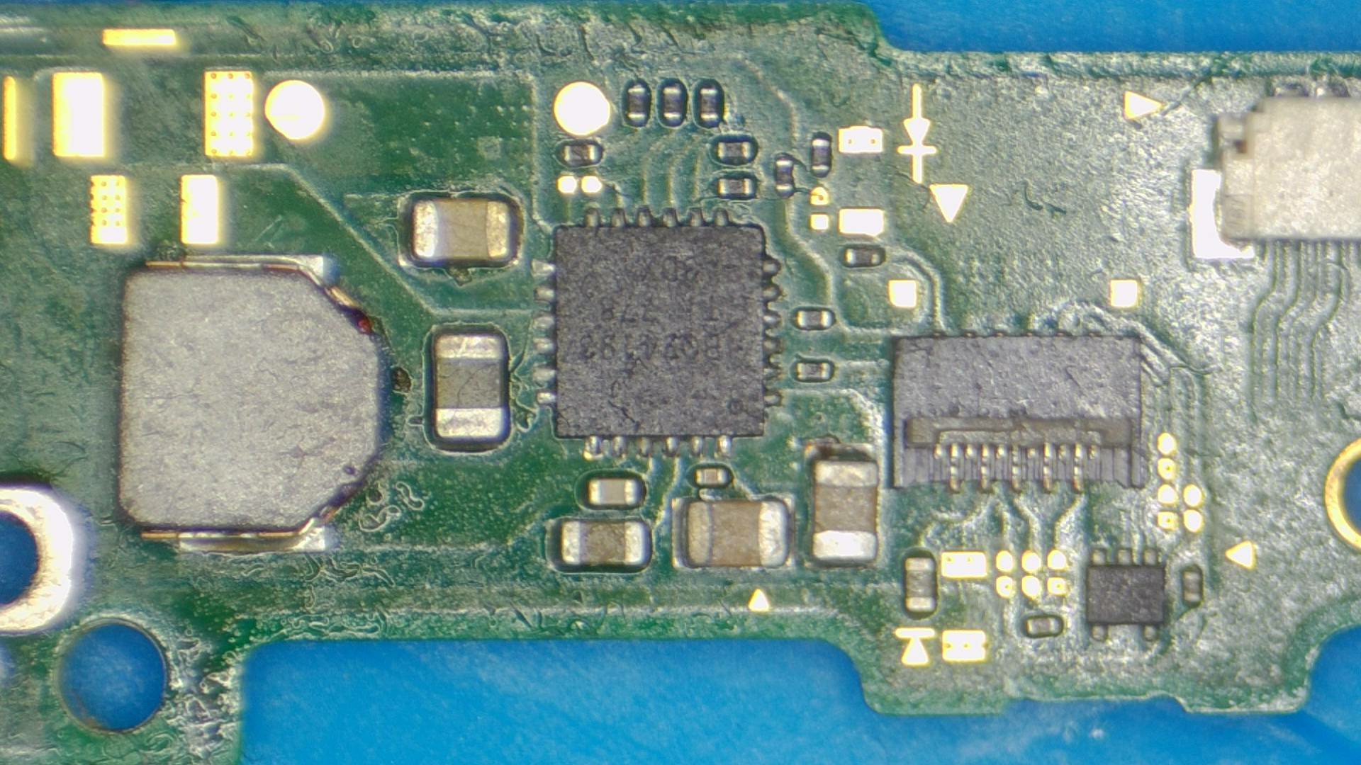
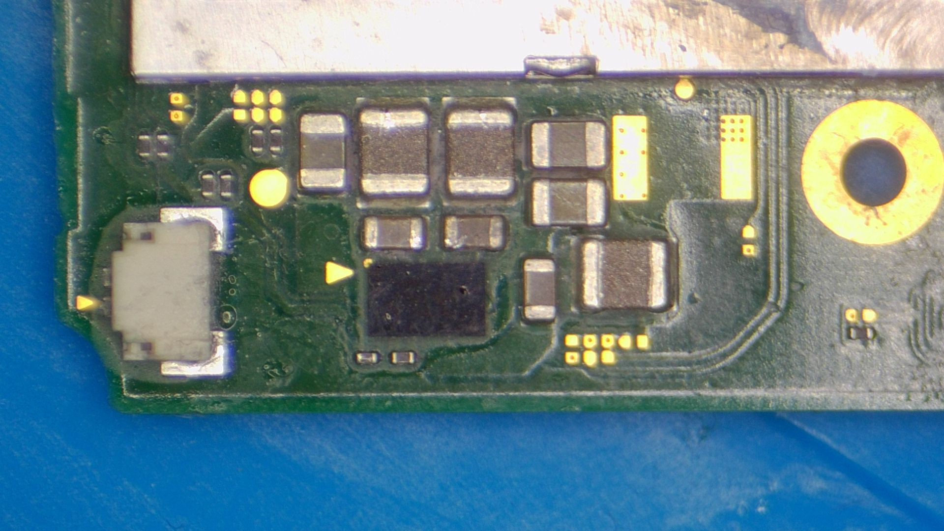
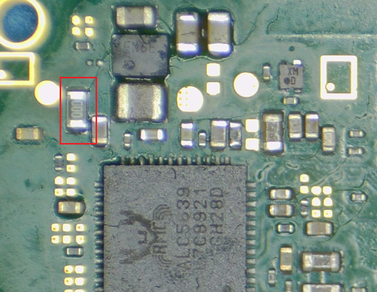
One think what I found although it is unrelated to my problem is that next to the ENXX IC on the left there is a 0Ohm resistor which was measured open interestingly.
I think they are one of the most useless and gimicky tools in this field, not only beause of there lack of preciision, terrible resolution and framerate, but mostly because they can not identify anything you couldn’t already identify with a finger or IPA provided that the fault/short is actually capable of exposing itself in terms of excess heat (low enough resistance to ground). In your case it would just point to exsting areas which normally get warm and offer no help. They might serve there purpose in car diagnostics or maybe a server system…
It’s not directly connected afaik, doesn’t hurt to change it out, especially if it has scorched/burnt plastic… which is always a red flag for me on any connector and is immediately removed and swapped out.
it’s possible there is a primary fault elsewhere causing a secondary fault on 3V3PDR, you would more than likely pick this fault up measuring resistance to ground on the M92 pins/pad and comparing to a known good, if you find anything out the ordinary then lemme know and i may be able to point you in the right direction.
Can you highlight that resistor in an image for me, an open wouldn’t be causing the issues your seeing on 3V3PDR, but it might be pointing to a secondary fault elsewhere or the original cause of the other fault
I will look around M92. But than I have to solder both P13USB and M92 back to have comparable test results.
The 0 Ohm resistor is on the following picture marked with ree bracket.
Ok I’ll look into this, just before i do though, can you double check that it is indeed open, they fail very rarely and it’s more often down to poor contact with meter probes.
Yes, It was open. I measured it 10 times. Even after removed it. If I am not mistaken these are usually used as fuses, right? Although for sure because of the 0 ohm resistance it is not blowing easily…
No worries, I’ll look into it.
Sometimes, though not alway, sometimes they’re just a placeholder for something else which didn’t end up happening or as a standard link as there was no trace space (jumping over something). But in this case regardless of it’s purpose, it acted as a fuse ![]() will know more once I’ve traced it out.
will know more once I’ve traced it out.