I made an error earlier, i made the assumption that removing the presumed diode would isolate 3V3PDR output from the rest of the board, I’ve since tested this and this is not an inline diode and as such it will not isolate it. So it’s possible the ENXX IC is at fault.
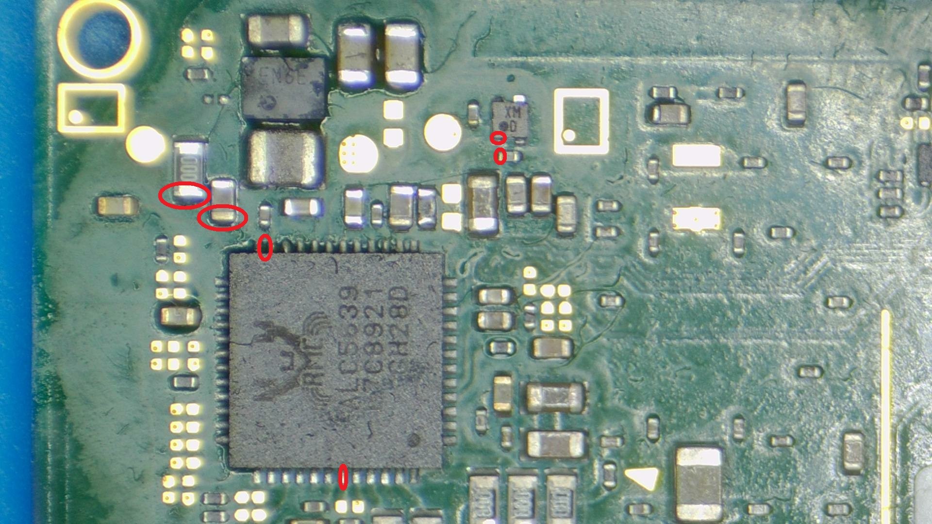
Checking the 0 ohm resistor, it correlates wiith pin 23 on the Realtek IC which is CPVDD, it directly connects to the following areas.
There are more areas with a direct connect, including a 1M resistor etc which are not marked in the above.
What caused the resistor to fail open could be a number of things, something getting on or around the presumed diode at some point, or same deal with the Realtek IC… I have not traced this out further or delved deeper into the microphone related stuff, maybe there is discrete circuitry elsewhere on the board related to this which may be the original cause.
Many thanks for wasting your time with my trouble. Today basically I pulled all the components what I could find on the 3,3V rail and nothing released my short. Now I also removed the ENXX and the short is still there so I really do not know what the hell is going on… Before removing the ENXX I tried to start it but maybe I already messed up something because it is not going on anymore.
For example what i assumed was a diode may actually be a linear regulator, the pad pattern on this IC matches that of parts manufactured by Ricoh, very much like the following https://www.n-redc.co.jp/en/pdf/datasheet/rp110-ea.pdf
Though this is likely not the exact part, i still haven’t checked if the part numbers match. This would make sense considering it’s connection to the pins on the Realtek IC.
As i touched on earlier, it is highly advised that you don’t plug in the battery or apply power to this board, doing so could damge other components and/or corrupt the EMMC.
I’ll have a think and see if i can come up with a few other points for your to test.
I have checked this data sheet and you might by right. The pinout fits perfectly. The chip enable is pulled high to the input rail. The only thing which does not match is the marking. But this could also be a customer specific part.
It was definetly not wasted time for me because my soldering skills improved a lot by removing all these small 0201 components But it is a little bit disappointing that I could not find the fault yet. The only chip I have not removed yet is the wifi chip but that one I do not want because I have never done reballing before (although I ordered balls already)
Would reccommend using solder paste and direct heat stencils for both the WIFI and EN IC’s, i use 63/37 chip quick solder paste which is excellent, stay away from pastes originating from china on either ebay, amazon, aliexpress etc and instead get it from mouser or some other legit distributor.
I’ve measured the IC size and it’s 1.0x1.0mm which means the one i linked to above is not an exact match, if you go to the following page, you can input the package name, which is DFN and the pin count which is 4 and all the 1x1mm IC’s are all the potential candidates https://www.n-redc.co.jp/en/design-support/package/
Not as far as i can see, it’s not connected to 1V8PDR supplied by the main PMIC. I’ll double check though
The 1.8V would come by way of the LDO… if that is indeed what this IC is
I have just seen this on the on the board diagra which is uploaded here but I measured it now and you are right, it is directly coming form that small LDO and independent from the 1,8V CPU rail fortuantely
I bought the exact same solder paste a few month ago from Mouser, so I will try to find some stencils. Are there any Nintendo swithc specific stencils (like for example for Iphones) or I should just check the package and order one whicfh fits to it?
If it is an LDO i wonder why they went with an isolated supply here… perhaps there was too much switching noise as it seems to relate to the microphone and speakers etc.
I just bought a bunch of iphone and android stencils which cover all IC’s on the switch less the Ram and SoC which require a more specific stencil… I’ll see if i can dig up the link for these
This also gives me a different perspective on the similarly packaged IC’s surrounding the WIFI IC, which again if they are indeed LDOs then that would make sense as it’s possible the switchinng noise if provided by the main PMIC would be to great hence the isolated linear regulation… though i haven’t measured the voltages surrounding this area aside from 3V3PDR being present
Today I also removed the MAX77620 from the back with the belonging capacitor because I saw that the 3,3V line also going there and still the same. I really cannot believe this…
The LED and a few IC’s near the fuel gauge are on this rail too… might be worth a look.
170ohm is such a strange reading and is more consistent with liquid or capactor damage than it is with IC failure… i think for the most part we’ve ruled out a bad caps with the IPA submerge.
 But it is a little bit disappointing that I could not find the fault yet. The only chip I have not removed yet is the wifi chip but that one I do not want because I have never done reballing before (although I ordered balls already)
