The LED and the fuel gauge I already removed. I could not find anything else there related to 3,3V. I also removed some FETs on the front and the back where I could find taht they are on the same rail. There is basically not a lot of ICs I have not removed yet.
Ultrasonic I do not have yet unfortuantely.
With IPA submerge I could not find anything. 200-250mW is not a lot though for small smds should be enough 
Might be worthwhile filling a pan with distilled or deionized water, if you have any flux cleaner add some, i use Chemtronics stuff as unfortunately you can’t seem to buy the Branson stuff within the EU, if your able to regulate your hob to maintain a pretty consistent temperature of about 50/60C then do so, rest the board on something within the pan and don’t let it sit directly on the bottom of the pan.
Leave it in there for about four minutes, then give it a scrub with a toothbrush then flip the board over and give it another four minutes and after another scrub, afterwards, submerge the board in IPA for a few minutes and finally put it in the oven at 60/70C to fully dry the board, you want it bone dry, failure to do this step will leave water between board layers which could potentially causing swelling during future rework.
This may not help or resolve the problem… but clutching at straws at this point 
I only have IPA at the moment.
I tried IPA buth again with no succes. I also tried heating up the board while measuring the resistance on the rail and basically the only sensitive area is the cpu. But I cannot find any connection between the CPU rails and the 3,3V rail.
I think I give it up now… Anyway I can see a low cahnce that I can put all the BGA back without issues 
maybe there is some sort of DIY short sniffer you could build, with a speaker… i haven’t tried to build one yet.
It’s not too bad once you’ve had a bit of a practice on a donor, i find the WIFI and PMIC to be one of the easiest to reball.
The only thing you have to watch out for with the WIFI IC is when tinning it with your iron (not touching the IC directly with the tip) is that you get them as even as you can and don’t linger to long as the polymer coating is pretty delicate and can burn off, which will prevent the pads from remaining isolated
I have just checked how a short sniffer works. Do you think it really works on a rail full of capacitors? They will just clamp the ripple I think…
I have heard conflicting reports… it’s easy to make products such as this look good on camera with an engineered fault, but in real world they could be terrible… so i don’t know tbh as I’ve never used one.
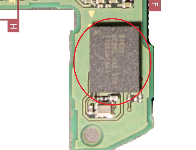
btw, did you remove the two caps next to the WIFI IC on this rail just to rule them out? Also have you pulled the custom ASIC? that’s also on this rail
Yes, I removed the 2 caps next to the wifi IC. I only found only those 2 there.
What custom ASIC do you mean? Where is it located?
I removed a few Mosfets on both sides, a PU IC on the back everywhere the belonging caps. Some additional caps. All the caps next to P13USB measured on this rail. Measured the resistor values conented to this rail. LED, Fuel gauge, MAX77620, Temp sensor IC, WIFI chip, ENXX, Realtek IC, all diode arrays, USB port, 2 small LDOs (what we think they are LDOs) and everywhere the capacitors conencting to the rail.
I mean it’s probably not this (asic) but worth a try
Is the EMMC connector in good shape, no crap jammed in or around it?
This one not, yet. It is maybe a good idea because jsut on the top of the picture the middle cap is on the 3,3V rail. I will pull it.
I saw that the EMMC also using the 3,3V rail and checked the connector inside outside already under the microscope and it looks perfect
Hmmm it’s at times like these you start to wonder if you have an internal board short…
Either that or you’ll find it’s the very last cap you remove… Sods law
Annnnd its not the ASIC 
I pulled each and every cap I could find on the 3,3V line all over the board. For sure there could be some I could not find.
There are only 2 MAX ICs on the front that I did not removed yet and the BQ. But around these ICs I could not find any cap on the 3,3V rail.
Could be that the accelerometer IC is also using 3,3V, that one I haven’t removed yet either.
It won’t be the two Max IC’s on the front of the board, they aren’t connected to this rail.
And there are 4 or 5 I assume small voltage regulators on the back of the board in a line. But there I could not find the 3,3V line.
Maybe try tinning all the pads of the currently removed IC’s on this rail and wick them, maybe there is a tin whisker or maybe the heat will relieve a board defect a layer or so down and the reading on this rail may change (?)
Cleaned all the bga pads now but not. Could be an internal short inside the pcb…
Maybe I will build one once…
- altered the resistor values on the comparator circuit, now only detects continuity under ~1Ω, basically a short.
Likely wouldn’t be useful as is for that reason 
I did not checked it in detail yet. I found an another kit for sale where it was stated atht with the higher sensitivity probe it can detect shorts from 10 - 1000Ohm also. But is costs $300…
ouch, be gutting if it didn’t actually work or led to more confusion