I’ve personally never had an ENXX ic get that hot, I would pull it then inspect closer for damage and if it appears fine then reball it, don’t just tin the pads with a soldering iron, 0.3mm solder balls should suffice
I’d agree ordinarily but given the experience level I’d first narrow this down based on what I said above - that, and this IC will get hot with a short elswhere on this rail just as a result of the higher current (this being the source and all), this can sometimes be a flase flag (which is why I tell all beginners to avoid thermal cams). if it does turn out to be this IC based on the diagnosis I mentioned above, then you can buy this IC preballed (doesn’t have any avaliable donors atm I imagine) my personal preference is paste and stencil mind as opposed to preformed balls if scavanging the part but to each their own ![]()
Hi @Severence and @PhynxVT ,
So I’ve been checking resistance on the 3V3 rail, and nothing stands out of the ordinary.
- Near ENXX: 21kOhms
- Pin 6: 21kOhms
- Near P13: 21kOhms
I’ve measured again the ENXX output voltage after booting up, and it’s around 1.1V, so obviously too low.
Following one of Retrosix’s guide, I’ve injected 1.2V on that rail. Only 30mA were drawn, so again, not really a sign of short (but what do I know).
My working theory is this:
- The board had a faulty USB port, which caused the M92 to die
- The port was badly resoldered, the switch wouldn’t work, and then it was sold (to me)
- The console was working on battery with a 2101-0001 error
- I changed the port and M92, but botched a pin on the LCD connector, causing the 1V8 rail to short to ground
- Also while replacing the M92 and chasing the components around, I probably overheated it, causing the ENXX to malfunction. Maybe a few balls melted?
So I’ve ordered a few more chips, including an ENXX (they’re hard to come by, btw). I’ve also purchased some 0.3mm balls, because why not learn that while I’m at it.
Indeed, I’m ordering the parts from China, which takes forever to get here every time.
Should I remove M92 and P13 to be safe, test again, then work on ENXX?
Thanks again, guys, this is so helpful.
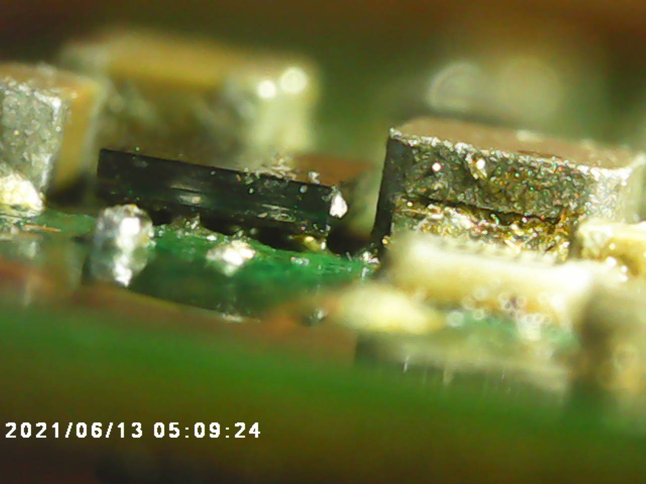
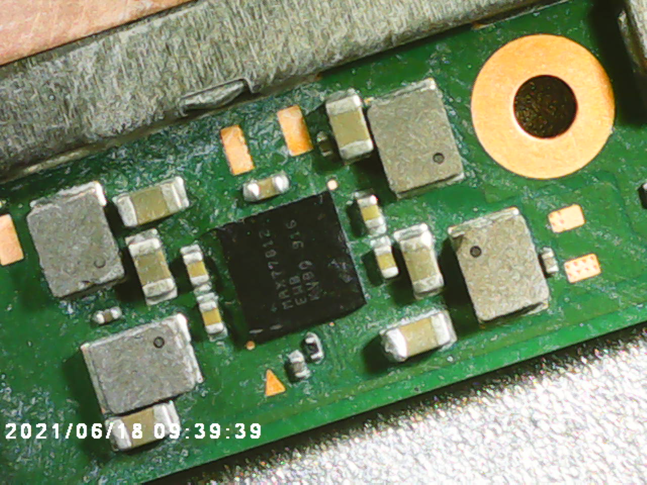
The ENXX ic does look wonky, also a short doesn’t have to be a dead short to ground, the 3.3v being pulled down to 1.1v means it is being shorted somewhere, i’ll upload an image that may be useful
2 Likes
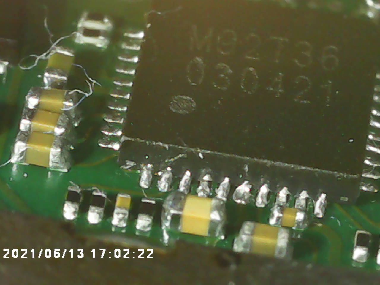
maybe im wrong on this, but is this not the ENXX chip?
2 Likes
It definitely looks like an overcooked s’more.
Thanks for the image!
Okay I think you’ve found it @PhynxVT .
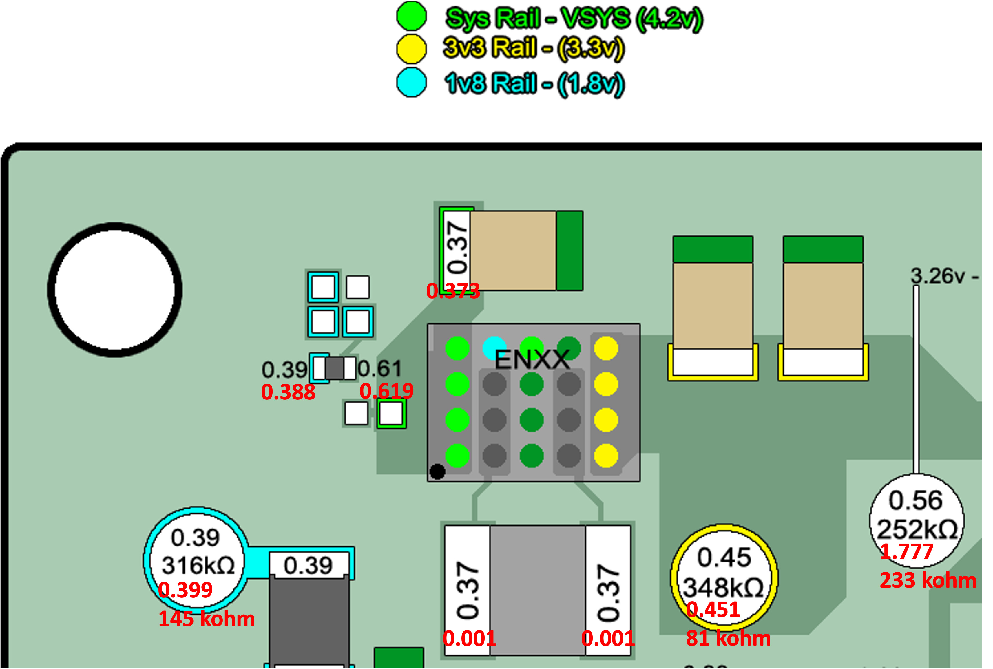
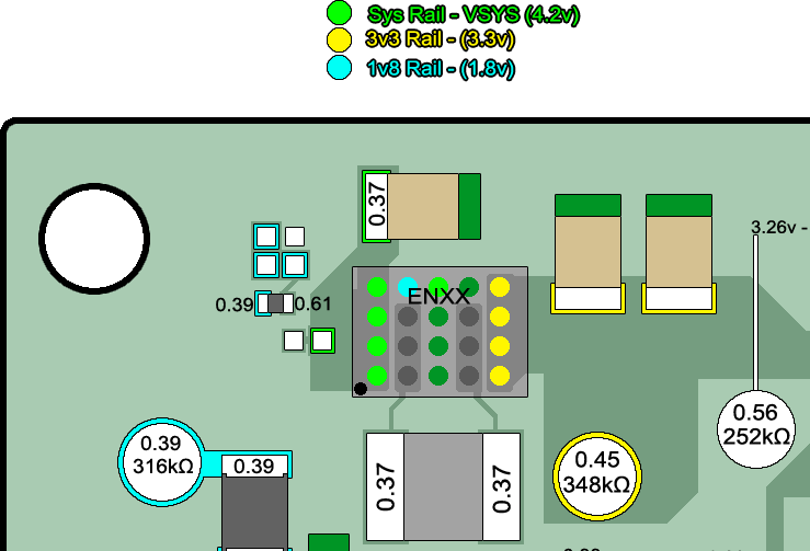
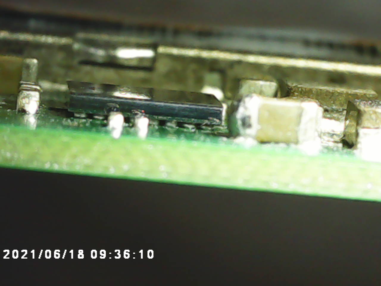
The inductor is shorting to ground (diode mode = 0V, resistance = dead short). From what I see here from another post
The inductor is connected to nothing but the IC. So maybe one of the balls on column B or D is touching ground on line C.
Time to learn how to solder an FPGA!
1 Like
So the rail isn’t shorted, (atleast not fully) and is in the realms of ordinary
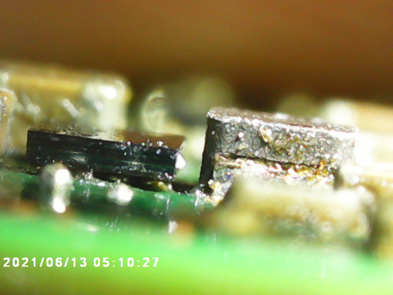
Looking at your images it seems somebody has bady “reballed” this… and by reballed I mean tinned it with an iron. Given how close one side of the IC is to the board my best guess is the chip has likely fractured internally (and possibly a bit externally but hard to tell from the image) likely failing open, and the 1.1V your measuring on the rails output is likely just parasitic. I imagine the IC failed due to to it’s close proximity to the board and the rework you did on the M92 the opposing side (not your fault - ordinarily it’d be fine)
Yeah not much point in injecting voltage given that the rail is not shorted, that is unless the suspicion is an active short scenario (rare) For future reference, imo, I’d avoid “injecting” voltage so early on in the diagnosis process in future, your measurments prior ruled this out and as we didn’t/don’t know what’s going on below this now suspected IC (and how it’s failed internally) it’s just not worth it (even if you think 1.2V is “safe” which it largely is but in certain circumstances it can not be)
You can get them on mouser or any of the other big suppliers - I don’t remember the part number off the top of my head (sorry @coda you might be right) but I identified it on the forum ages ago which you should be able to find/verify with a search.
It’s easy when they’re preballed. don’t worry (even easier than the other IC’s you’ve worked on) - just pull the chip, tin the pads, wick them, flux, pop the new IC on and away you go ![]()
1 Like
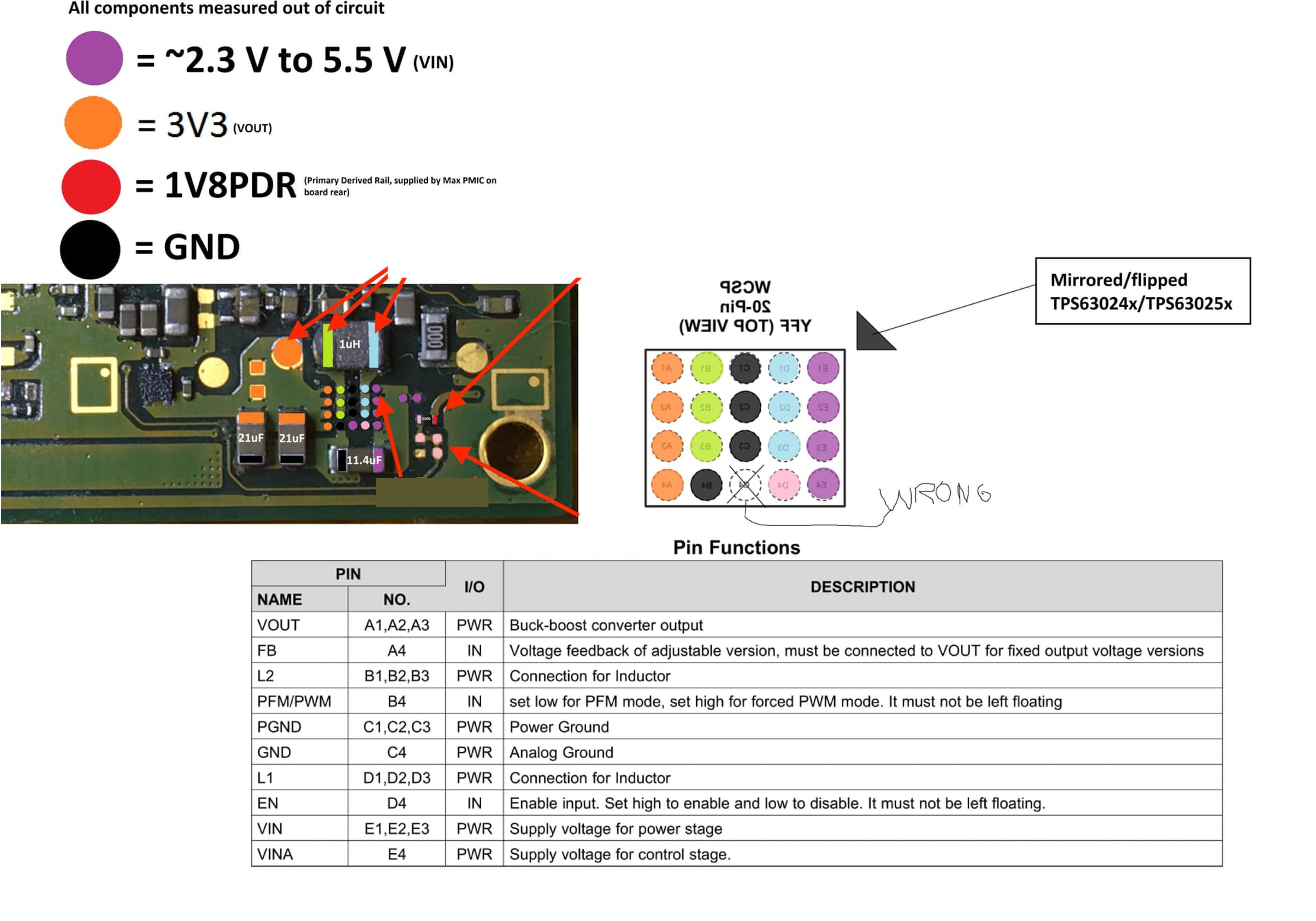
The testpad that you get 1.77 vs my 0.56 indicates a bad connection on your m92t36 btw, you may want to take a look and check each pins readings
1 Like
Which would totally explain the cotton fibers, now that I think about it.
Thanks for the positive reinforcement! It didn’t feel great thinking I caused it.
Duly noted. It seems like a such shortcut for so many Youtubers, though. They probably fry stuff without even noticing, and then call it a dead APU…
Al-riiiight, let’s do this!
Looking forward to getting those new chips.
You’re right again, I found it: pin 4. It was testing fine yesterday, the joint must have been weak. Easy to fix.
you got this, small BGA chips are simple installs my man. Id much rather install a 20 ball BGA than a QFN, I suck at QFN’s lol. Just remember to lower your airflow and hover above the chip farther than normal and then move closer. Its been my own experience that BGA’s tend to catch an air current easier than most.
2 Likes
Sorry missed this. You have to watch yourself getting ICs from China as while sometimes they’re fine - in the case of unmarked parts (for example if the listing just says “EN IC” then likely thery have no idea themselves what the part is and they’ll either be salvaged and poorly reballed or physically damaged or they’ll be a clone IC (or worse a re-etch/laser of an unrelated IC in the same package)… or they could be legit… it’s a coin toss. Given that you can get this at most legit vendors I’d opt for that before anything else…I only ever use Aliexpress/eBay China these days if I can’t get the parts from a legit supplier and/or I’m desperate, just not worth the headache.
Got a whole bunch of fuel gauges for Switch on Aliexpress ages ago. Literally no good reason to pull, reball, retop (in some cases) and then re-blister then ultimately resell… given how common and cheap the IC is new… but they still did it ![]()
Here is the topic where the IC was identified.
As for replacing M92/P13 no you should be fine, provided all your rails measure good (like we did earlier ) following replacing the EN IC en you should be fine.
Your exactly right:![]()
Since I haven’t received the new ENXX for Switch #2, I got back to switch #1 and swapped the MAX IC under the SoC. I still get the exact same behavior (60 mA current draw at 15V, turning on and off when pressing the power button, missing 1V3 power rail) though. I might need to swap the fuel gauge now, or maybe there’s a chance my soldering was bad.
I followed your advice @Severence, @coda and @PhynxVT, and I think it went pretty smoothly, though. I also thought it was easier than large QFNs, @coda!
Wicked it:
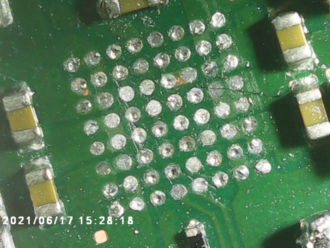
Heated it until it seated itself on its own:
However, maybe some of these balls are not making a good connection.
But then I thought: why not look at the board with my thermal camera, just in case.
And it seems the NAND is warmer than the rest.
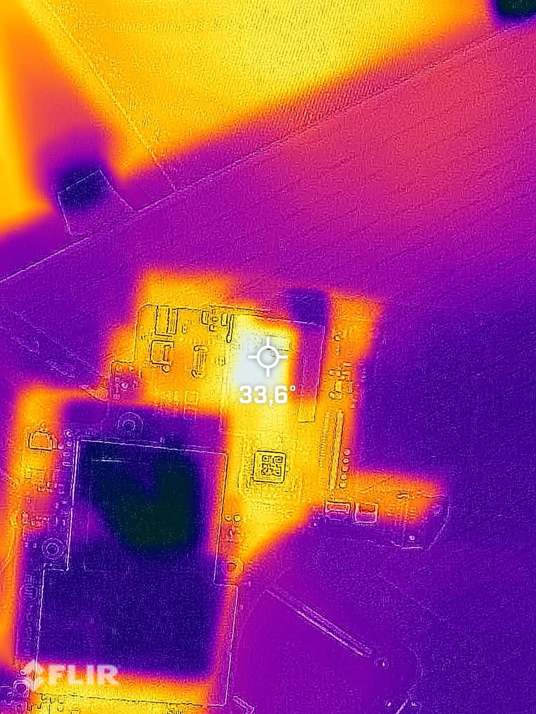
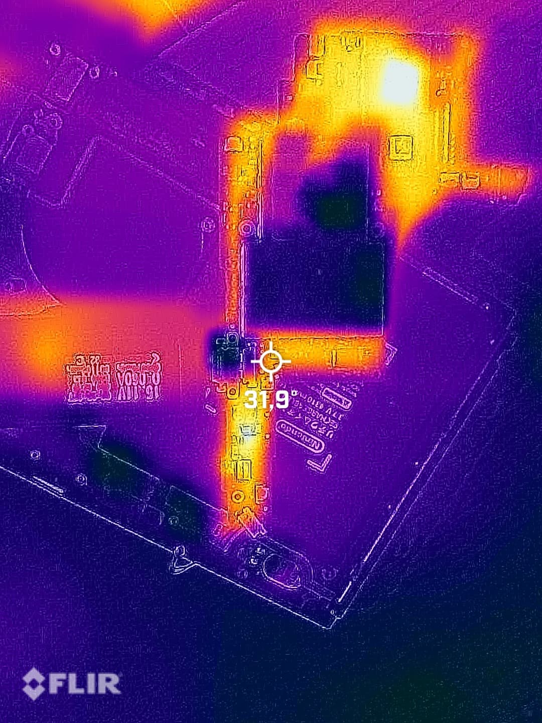
What do you guys think?
The whole board looks close enough in temperature so I wouldn’t worry about it, thermal cameras can send you down a rabbit hole sometimes
Also the 1.35v your missing is generated by the main power ic on the back of the board, the max77620H in this case, max77620A for v1 boards, not the max ic you’ve swapped
Note the two max77620’s are not swap-able, at least never worked for me
Makes sense, but couldn’t something else prevent that rail from being activated? Eg. Fuel gauge, buck reg, M92…
By « not swappable », you mean that H and A are not interchangeable between revisions, correct?
Yes, A and H are not interchangeable between board revisions,
The 1.35v could also be missing if it is a shorted line but I believe you checked for that?
Do you have your 3v3 rail?
No short on the 1.35V rail, and 3V3 is working fine.
Where did you get this chip from?
Just for future reference. I can tell from your image that your iron was not delivering enough heat and you were pressing a touch to hard, for next time, apply barely any pressure to the wick, let the flux and heat do the work, if the pads aren’t winding up totally flat by the end (which yours aren’t) then suggests not enough heat in the board… if your finding your iron is simply not capable then use your hot air alongside at approx 150C to give it a helping hand. If your seeing the solder mask coming away (can be seen in your image) it’s indicating your pressing too hard on the wick.
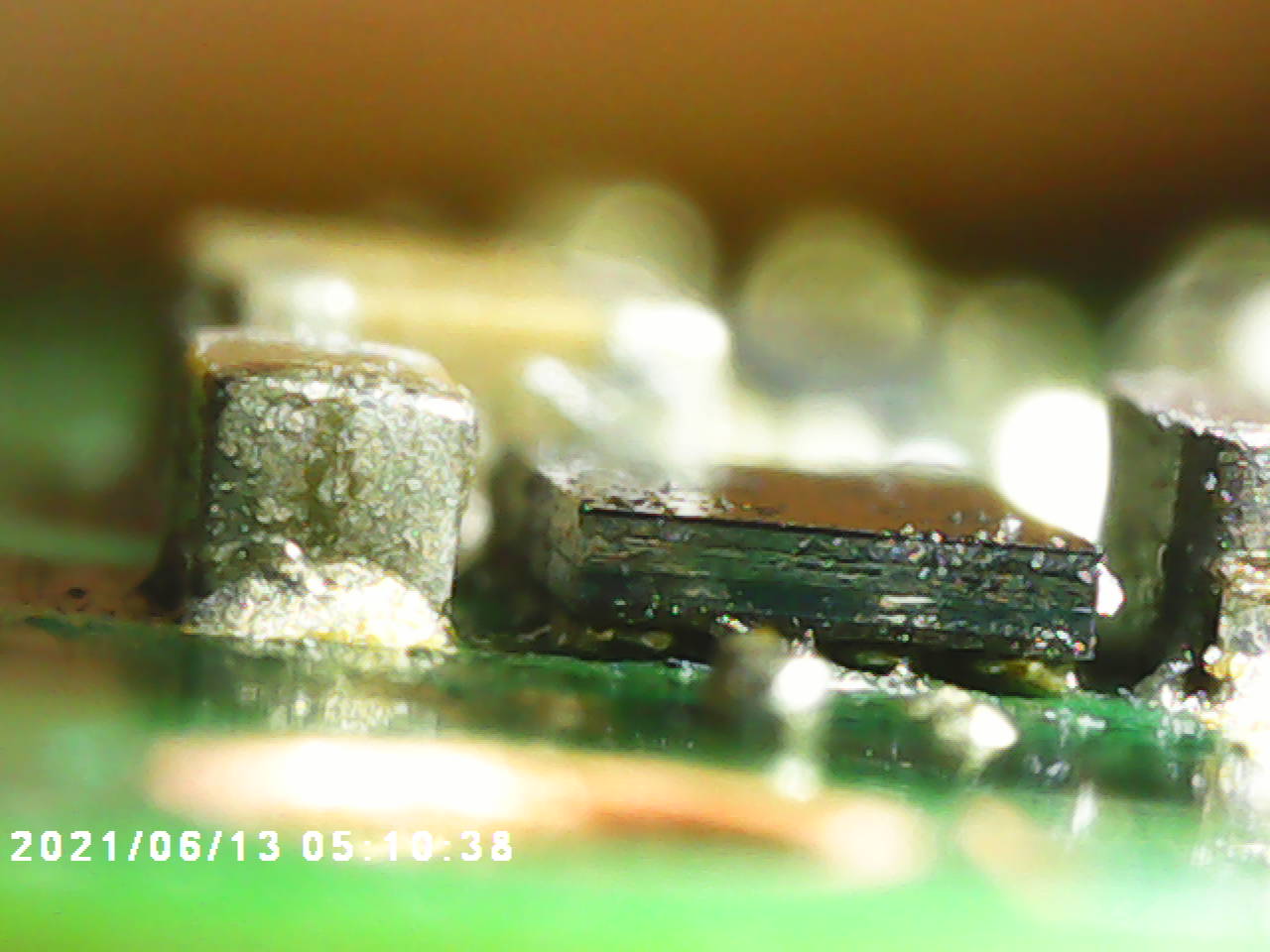
It’s possible I suppose. as those joints don’t look amazing (you’d expect those balls to be as atleast as shiny as the lead free solder used on those caps nearby) but could also be your flux is coating them- it does look a bit smeary from the other images. What brand of flux are your using?
To add - Looking at the images, I don’t like the look of that resistor just below the IC, probably been hit a few times when you were wicking. It’s probably fine but I’d swap it out if it were me regardless.