Hi guys.
I am working on a customer device, the customer states they left the switch on a dock for a long time and had not played it for quite a few months, they went to turn it on and nothing.
Plug in the console to USB and drawing 0.003A, virtually nothing.
USB-C Port has no visible damage, and upon inspecting the board there appears to be no visible damage. I checked the caps around M92T36 and there are no shorts.
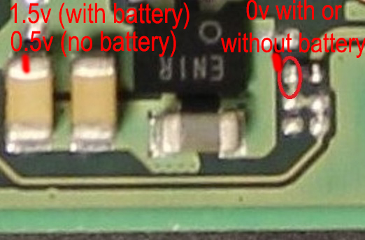
I have 5v going into Pin 5, but only 0.4-0.5v coming out on Pin 6.
In the past this has either been M92T36 or P13USB, or a combination of both, so I replace both chips and the issue persists. Thinking I have replaced with bad chips, I replace again, and the issue persists. I’ve triple checked my work and all appears fine. I have noticed there is only 0.5v going into P13USB from M92T36.
Hi, I actually saw both those topics before posting.
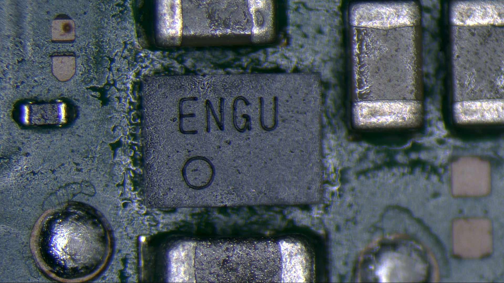
Problem is I don’t have a spare battery (the customer’s is flat) to test with a boot - however the 1.8v and 0.69v points from that post both get 0v on USB power. I tested the cap near ENXX IC and getting around 106k ohms.
So the ENXX IC is not being told to enable the output, so you won’t get your 3V3PDR and won’t measure it at pin 6 of the M92 IC or at the larger cap of the P13
I don’t recall if a semi charged battery is needed for the SoC to enable your 3V3PDR but it might be worthwhile charging the battery up externally and going from there to rule this out, chances are on a semi charged battery you’ll get this rail back, which might point to an issue elsewhere (charging issue for example)
I wouldn’t do it in circuit, I’d tin some enamel wire, jam them in the battery JST connector, then hookup a bench PSU to these tinned wires, 4V with a current limit initially of 100mA (i guess it’s completely flat) if it refuses to take a charge, driop the voltage down.
once the voltage increases to 3.6V you can increase the current limit (say 500mA). and once it’s at 4V that should be charged enough for testing.
Okay… so the plot thickens.
Charged up battery to 50% and connected board back up.
Console turns on, and when USB-C is plugged in, it will show on the screen as charging. Flip the cable around, same thing. Still get 0.5v from M92T36 Pin 6, and 0v at battery terminals. It also continues to pull 0.003A from USB-C. Where to from here?
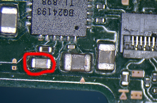
I also just discovered that below BQ24193 this cap appears to be shorted. I remove the cap and the short is still present on the board. Checking on a donor board, this does not appear normal (however the donor board is also missing a lot of components…)
afaict looking at the datasheet briefly, your shorted pin is REGN, and looks to be internally generated by this IC, pull the IC and see if the short clears, if it does that’s likely your problem.
would guess this is somehow dragging down VBAT or your SYS rail which is causing your odd results on 3V3PDR etc.
Either battery doesn’t have enough charge to maintain =>3.8V under load, or something is dragging the voltage down.
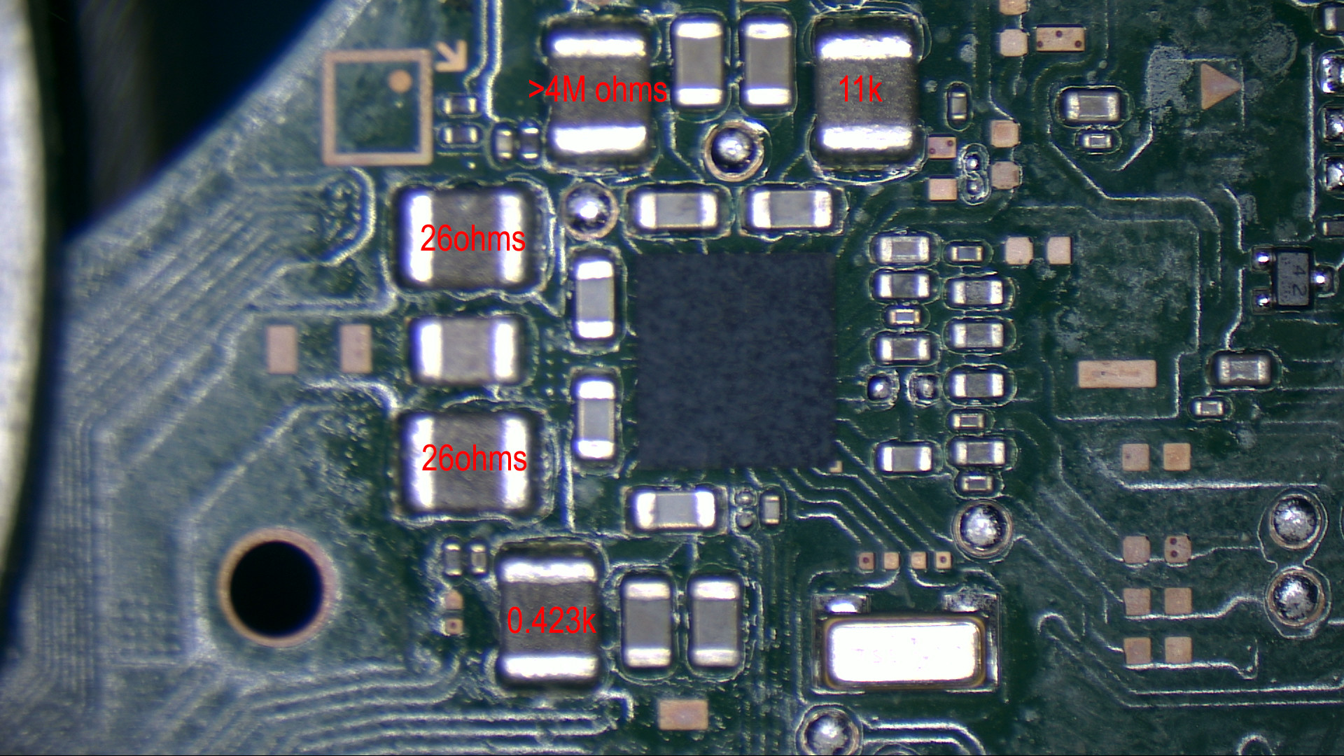
on the mianboard, with black probe on ground, no battery/power connected, and your red probe on the positive battery terminal, what’s your resistance?
After that, can you do the same thing but with your red probe on either side (doesn’t matter which) of the 2R2 coil near BQ IC (SYS rail) and let me know the resistance here too?
You have a “high” short here, would normally expect somewhere in the region of 10K, this is an odd reading, it’s possible you have a short elsewhere and this is as a result. but just incase, double check this rail on your known good board and compare, it’s entirely possible your meter is playing silly buggers
Any of the caps surrounding the BQ IC look dodgy?
Can you do the same thing on the inductors surrounding the main max PMIC on the reverse side of the board and let me know your resistance readings?
 Thanks for your help.