Oh sorry.
After reading your post now i removed the audio chip and the short is gone…
What should i do next?
You have to make sure thiere is none.
Refrain from powering on the console until you are sure you have resolved all faults and have absolutely no bridges elsewhere… less you kill it entirely
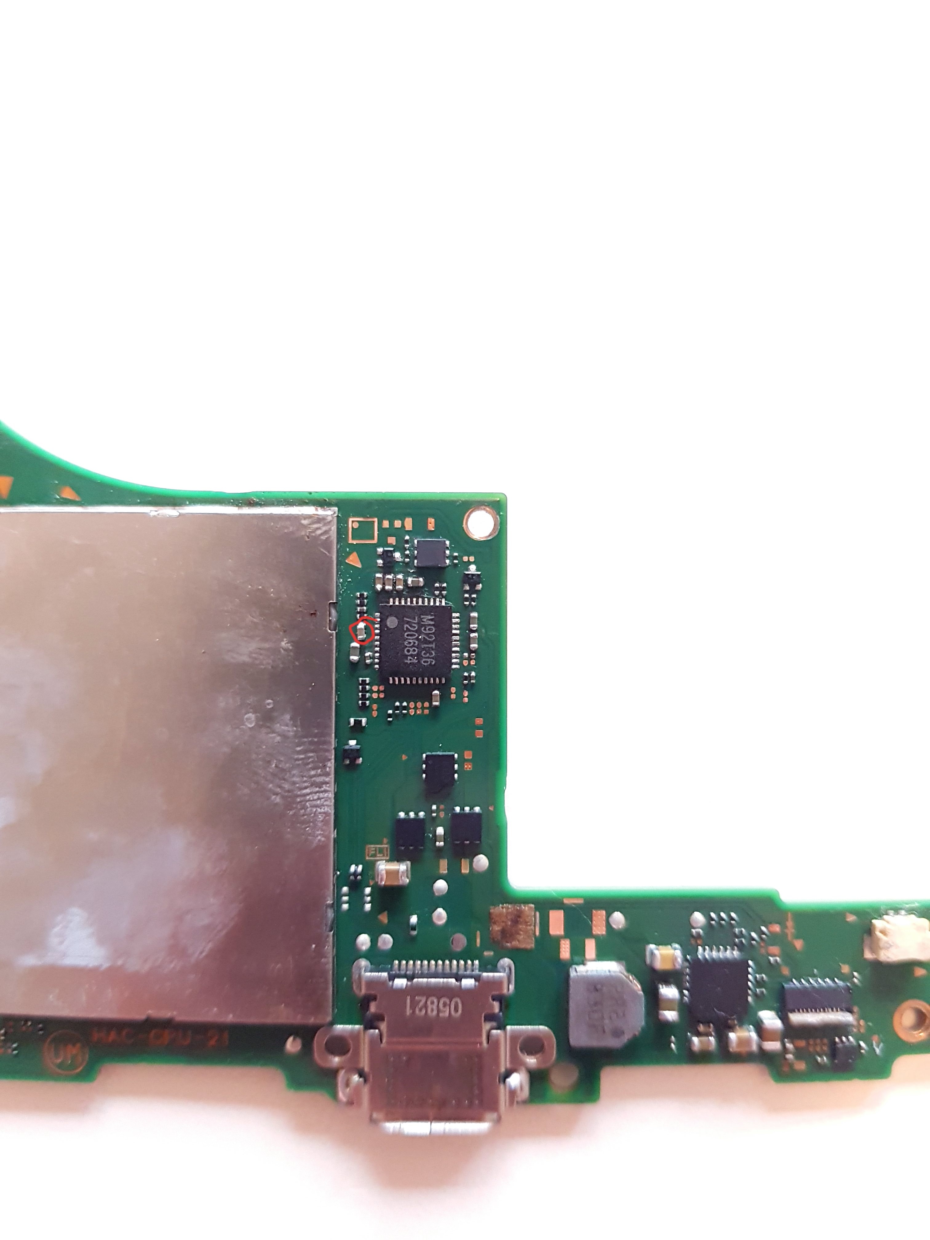
Looking at your photo. your BQ IC is still on crooked, seems to be lacking solder in some areas and i can also see solder debris/bridges across pads. are you using flux?
I can’t make out the M9 IC from that image
Im gonna remove this component and look if there is a short. But not today. First i have to buy a new Soldering tip and some solder, my soldering tip has a hole on the tip of it.
Do i have to order a new ALC chip? If yes then i would like order other Chips, if there is any other chip i should replace.
Yes im using flux.
Good plan!
Would reccommend picking up a T12 station, Ksger has a budget station which is great for the money as you can calibrate (neccessary) and save temp profiles for each tip. get a D12, D24, BC2, JL02, and a J02 and your all set.
possibly, it might be fine though, it was likely just a solder bridge causing the previous short, when putting it back on, test for that short again, if it’s the same then the IC is likely bad.
Pick up another M9 and BQ IC incase all the bridges and subsequent power ons have killed one or both of these IC’s.
Take your time, don’t rush, don’t power on the board until you can verify there is no bridges across any of the pins/pads and the IC’s are perfectly aligned (indicating a good even tinning), practice makes perfect… everybody skips this step but it’s crucial in order to get to grips with this sort of rework, a donor board doesn’t care if you give it too much heat etc ![]()
btw i wouldn’t be surprised if the low melt solder caused or accelerated this… the stuff is pure evil ![]()
Also, pick up a few USB connectors while your at it, if you used low melt prior, you’ll have to remove it and use regular (quality) leaded solder for the replacment, you will melt them the first few times you try to replace and they will require replacment, again this comes down to practice again, if you need help in this regard then just say so, I’ve made a few posts on here which i’ll dig up on how to change the USB properly ![]()
Ok thank you for the hint. The most time i used the normal solder. But at the end when i tried to remove the bridges and reflow the bq i used the low melting solder…but i noticed that this solder is really bad so i stopped working with that.
Another question…is there any way to check the hidden pins of the usb port on good connection?
Yeah, you can pick up a USBC breakout board and buzz it out end ensure relevant points are making it to their destinations, you can also do a quick and dirty diode test on the breakout and see if your readings match up with the various diagrams posted here.
Soo…today i removed all bridges (which was a hard task to manage) and put a little bit more solder around all chips so that these upper pads on the chip gets connected as well.
But still the same result…0.00 volts on my usb meter.
The battery is fine it has 3.6 volts.
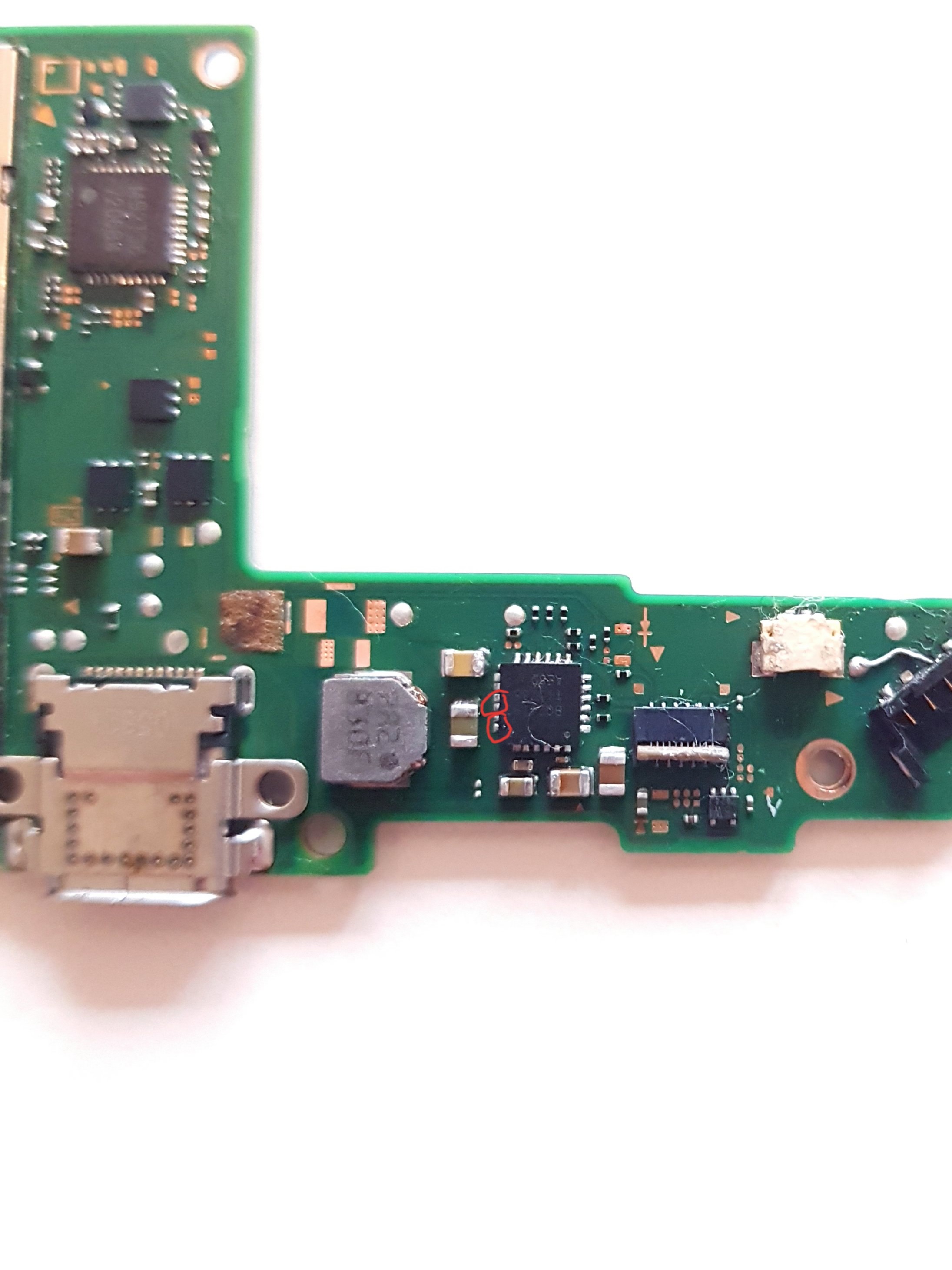
Short on this little capacitor left to the alc chip.
I also have a few shorts where the cpu is.
I think im gonna wait for the new Alc chip and change it. I also want to reflow the bq chip because i think there is not enough solder underneath it. I thought i dont want it to squeeze out under the chip.
What do you think i might have to do?
Hey.
Im gonna work again on the switch today and i was thinking about something…what if i put voltage from a desk power supply into the mainboard and put freeze spray or alkohol on the shorting area and search for the shorting component?
Next question would be…what voltage should i put into it and where should i solder the plus wire?
Maybe on the fuse above the usb c port and put 5 volts on it?
No don’t do this, you will likely kill the SoC somehow.
Just because your getting zero volts on your meter doesn’t mean you have a short somewhere. Can you confirm where your trying to measure voltage on the board?
The IC is likely bad, replace it later.
Likely not actually shorts, normal.
As i mentioned earlier, do not connect battery or USB to the board while there is a potential short elsewhere (Realtek IC) less you permanently damage it
Can you confirm the brand of solder and alloy that your now using?
Im not measuring voltage…i dont know where to measure it. I only measured at the beginning of the project, that 15 volts of the ac adapter are going to the small 0201 cap on the left of the m92 chip.
Till now I just measured in continuity mode.(beeping mode).
I have to look later if it arrived.
The brand is Stannol its a German brand and following things are wroted down:
Alloy:
S-Sn60
Pb38Cu2
Type:
HS10
Fg.2,5%
0.5mm
Seems fine. I take it you removed the M9 and BQ IC’s and wicked up all previous low melt solder at this point and refitted with your new alloy?
Check the forum in the switch category for the fuse - check it’s not open.
Check your getting continuity from the USB pins (via breakout) to the various corresponding points on the board and/or check the diode mode reading against the various diagrams posted here.
Check the ESD diodes if present on your board, search the forum in the switch category for relevant location and how to test.
Once you’ve verified all the above then we can continue ![]()
Ok I’m going to test it today…if I can find the posts where those informations are.
Thank you
So…I checked the fuse above the usb port. It’s fine.
I also replace the red highlighted capacitor because there was no resistance. After I replaced it, it shows me resistance (can’t remember exactly how much).
The pins of the port seems to have connection to the pads it has to…
The only thing I didn’t checked were the esd diodes because I didn’t found anything in the forum where they are and how to check them.
And I recogniced that the bq chip has bridges because the pads under it are very close to each other I highlighted them (but it’s not how it looks now it’s the photo from the beginning of the project)
Sorry, I can see from your pictures you don’t have the diodes present on your revision board… so don’t worry about this.
If you haven’t already done so, remove the M9 IC and BQ IC and wick up all low melt solder that was previously used on both the board and the IC’s
Tin the pads with your leaded solder (nice fluffy pillows) with considerably less solder on the center pad/s, then, also tin the outer pads on the IC’s themselves. Add flux, put a shield over the plastic connectors (if needs be) and reflow the IC’s into place.
If with the Realtek IC present on the board you still see the short on the surrounding cap/s then leave it off the board for the time being and install the replacement later when you receive it.
I don’t recall if the switch will boot or boot with an error code with the Realtek IC removed… so you may have to wait for your replacement to arrive to fully verify the repairs were fully successful.
Even so, you should still see current draw at this point, so after you’ve verified all your IC’s are correctly installed and your sure there is no bridges and test fine etc and once you’ve ensured your USB connector has continuity to it’s relevant corresponding points via a USBC breakout board then you can proceed to plug in battery and USB and monitor current.
The ALC chip arrived today and i changed it, touched the pads with with soldering iron around all chips but same result.
With my phone charger my usb meter jumps from 0.05 to 0.13 then to 0.07 and this the hole time.
With the original cable i see a charging symbol on the display which is a small success.
But the switch won’t boot.
I see the Nintendo Logo (not the switch logo),
it stays for about 1 or 2 seconds then black screen again.
I have to hard reset the switch to get to this point again.
Did you wick off all the low melt solder on this and the other IC’s and the applicable areas of the board?
0.13a can indicate either a completely charged battery or a completely flat battery. try leaving it on charge for a few hours or safer, disconnect the battery and charge it up externally in order to verify it is indeed charged… or measure the voltage on it.
Failing that, time to look at the battery connector and/or fuel gauge i suppose.
Ok after resolder the battery connector, my usb meter was showing me 0.41v. But no turning on. After the Nintendo Logo, the low battery indicator appears. So i left it over night on the ac cable. Today in the morning the Switch was showing me the homescreen! I thought finally done with this switch.
But after that i disconnected the battery to connect everything else and put the case on and connected it again.
And then the same issue appears again… but the battery icon was full and green.
I gonna try to put the mainboard to another switch, maybe the display connector or something is faulty…
Or maybe i can solder the cables of the battery directly to the pads? Maybe the bridge i soldered to the connector has a bad connection?
Ok this is weird…I’ve let the switch for a few hours on the charger after the switch logo and the homescreen is on again.