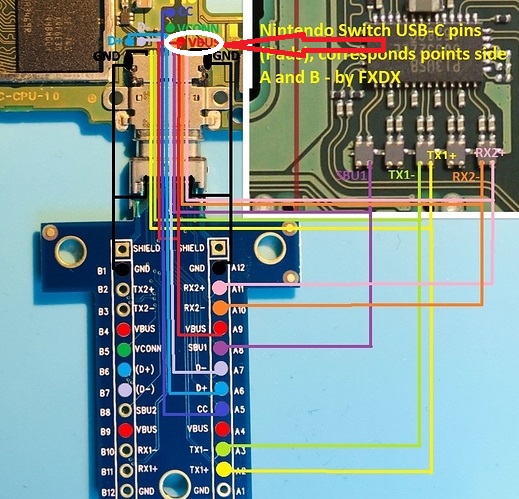
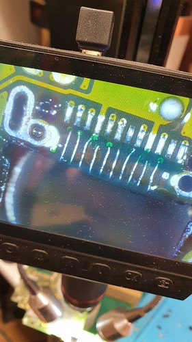
There’s a YouTube video that shows repairing of the USB-C port. I can’t post links but the title of the video is: Nintendo Switch - Charging Port Missing Pad Repair
Fxdx, what/where did you purchase the USB port?
The type I am getting sent are not “exactly the same” as the original port as the original you can access the hidden pins from underneath slightly. The ones I have been sent you can not.
Did you modify the port at all when using the ribbon cable?
You have to dremel into the metal casing and remove some of the plastic inside the connector
On the “clone” ones you can access the pins by slowly removing the stuff until you reach all contacts of the connector
I find the clone ones better, you can bend the needed pins up and solder some wire to them in order to restore the connection
Thanks. That makes sense.
I have managed to solder a ribbon cable onto the hidden pins row, I’ve checked for continuity/shorts/bridges seems ok, I will attempt to jump wires to the alternative points when my solder mask gets delivered.
any chance have pinout for the switch lite.
I recently received a switch lite cc2/cc1 line has no value.
Maybe that helps
I think you swaped the sbu1 and cc1 around (red lines on board) 5 is going to cc1 and 8 to sbu1.
You are right. Editing error. Thx
so the vbus is just connected to what?
in the 8th picture it shows 2 connectors going to the front of the board but in the diagrams it doesnt seem to do that whats going on there
They go to the other side to vbus and it appears here in the picture.

fyi, in your original pics you can dig out the two outer ground pads which you ran the two enameled wires via the holes. It’s just ground plane below so it’s safe and neater.
Hey what gauge of magnet wire did you use for this project
Very well done. Good job Bro.
You look amazing.
I tried in the same situation, but I forgot that only half of the usual solder was attached, and because I connected the adapter strongly, the other half of the pads were also removed. 
Needs more careful treatment
great job,
quick question: how thin was the solder mask, did you heat up from the bottom or the top of the usb port.
You need to get the solder mask as thin as possible as the connector won’t sit well. You can try to tweak the pins of the connectors down so that they can take up the slack if it makes sense.
I heat from the bottom. It’s a tricky operation as seconds too long, and you melt the inner plastic of the connector, so you need to be quick and ready.
Don’t forget to tin the pads of the connector and the board to maximise bond. And plenty of flux!
how do you clean the initial flux off after soldering the jumper wire? each time I use a q tip it just moves the jumper wire out. Do you tin the jumper wire after the solder mask? Great idea on tweaking the inner rows on pins so that it can try to bond with the jumper wire.
Yep. That’s a pain. So long as you have a good connection, you can afford to disturb the placement whilst you clean. I often use a soft bristle toothbrush and brush in one direction to minimise pressure on the bonds. Once free of flux, you can reset positions ready to apply UV mask to insulate and provide mechanical support. This is an important stage as not getting all flux off well compromise the bond of the mask.
