NintendoSwitch(hac-cpu-20) no start

※ This text has been translated from Japan using Google Translate. I’m sorry if it’s hard to understand what you mean.

Nintendo Switch (hac-cpu-20) receives 0.6A but does not boot

I don’t see any shorts around the PI3USBchip and M92Tchip.

There are no visible signs of short circuits

I have basic tools such as soldering iron, heat gful if you guys could tell me

Please help me, my distant friend

Hi, no worries. Just try include pronouns like 私, あなた, それ, これ etc in your Japanese before translating, I understand that for you it’s clear from context but when it’s translated into English we lose all of that and without the pronouns it’s hard for us English speakers to understand what is being talked about :slight_smile: . Also feel free to include the original Japanese text too, my Japanese skills are really rusty (or just plain bad in general) but I may be able to read / understand a little if somethings lost in translation :+1:

for example, your sentance

I’m sorry if it’s hard to understand what you mean.

without the pronouns the translator is making the assumption that your talking about the other person (us) being hard to understand, by saying “you mean” (あなた) instead of what you actually meant, which would be 私 . So I think your original sentence in japanese would be closer to

私が言うのがあなたにとって理解しにくい場合、申し訳ございません。

Which I imagine will seem a little wierd or perhaps very specific for you, but it provides full context and translates back to

I’m sorry if what I say is difficult for you to understand.

Which I think is what you meant :slight_smile:

Anyway, can you tell me what led to the current failure mode of the Switch? Or did it arrive to you in this current state?

1 Like

ありがとうございます!

日本語が理解出来るとの事なので日本語で質問させていただきます

Switch(hac-cpu-20)が起動不良になり0.6Aから立ち上がりません

よくあるPI3USBの周りも特にショートは見られませんでした、同じくM92Tの周りにもショートは受けられません

目に見えて焦げてるチップも無く、行き詰まった状態です

何かヒントがあれば教えて欲しいです。

はんだごて、ヒートガン、マルチテスターなど基本的な道具はあります、ジャンクも複数台あるのでパーツもあります

最後に、返信してくれた事を心より感謝します

:sweat_smile: haha I’m really, really bad, my grammar skills are severely lacking and I’m only practicing input and not output, so I’ll primarily stick to English :slight_smile:

how did the Switch console end up in this condition to begin with? or did it already come to you in it’s current condition?

(same as above) Japanese:
“このSwitchのコンソールはどのようにしてこの状態になったのですか?それとも、最初からこの状態で手に入れたのですか?”

1 Like

I changed the translation from Google Translate to DeepL

This Switch was available for repair and the owner said it suddenly stopped working.

There is no other information, and there is nothing more than a visual inspection of the circuit board.

However, I’m in the process of looking into it because the condition is similar to when the EMMC was removed.

If you have any other clues, I would appreciate it.

I see

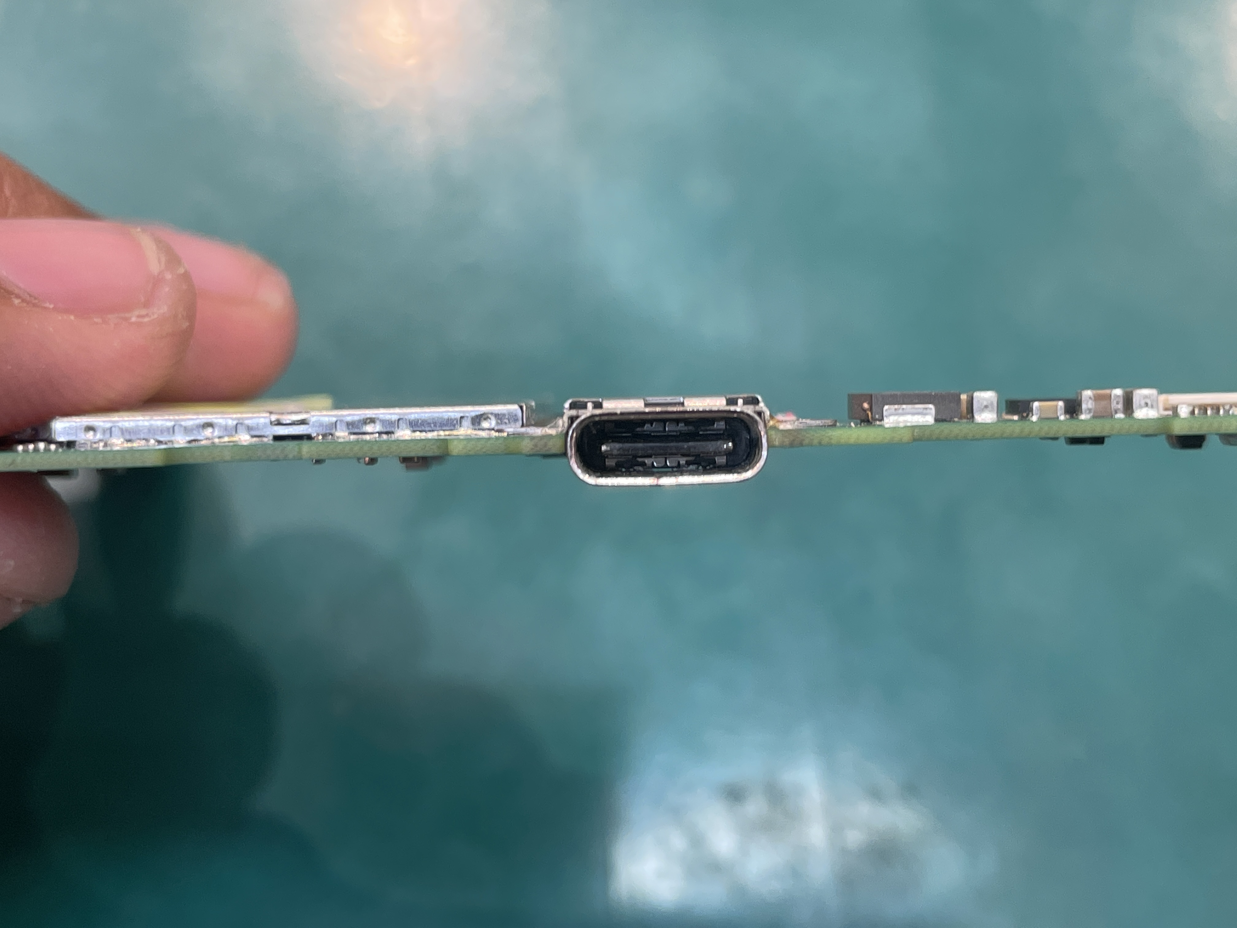
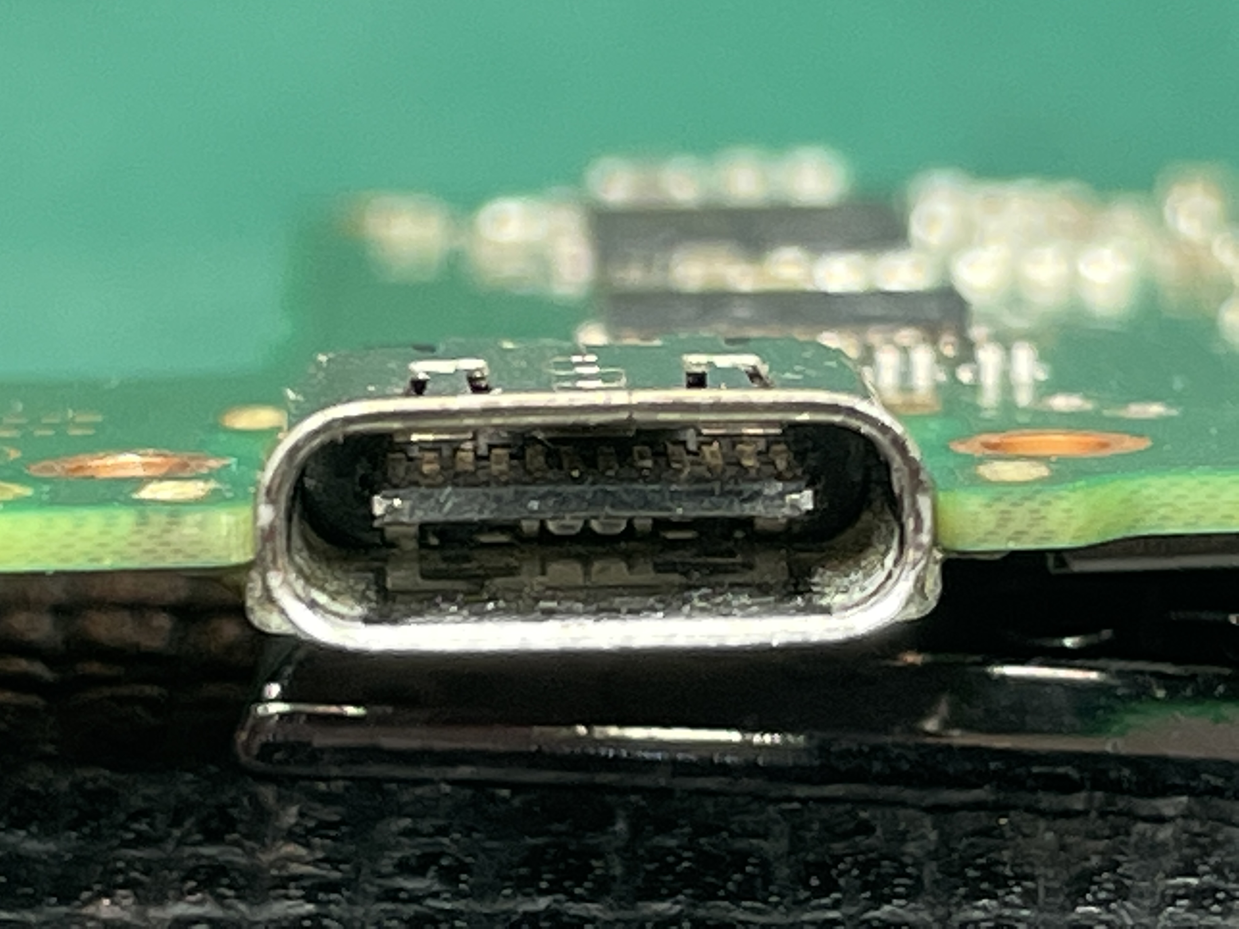
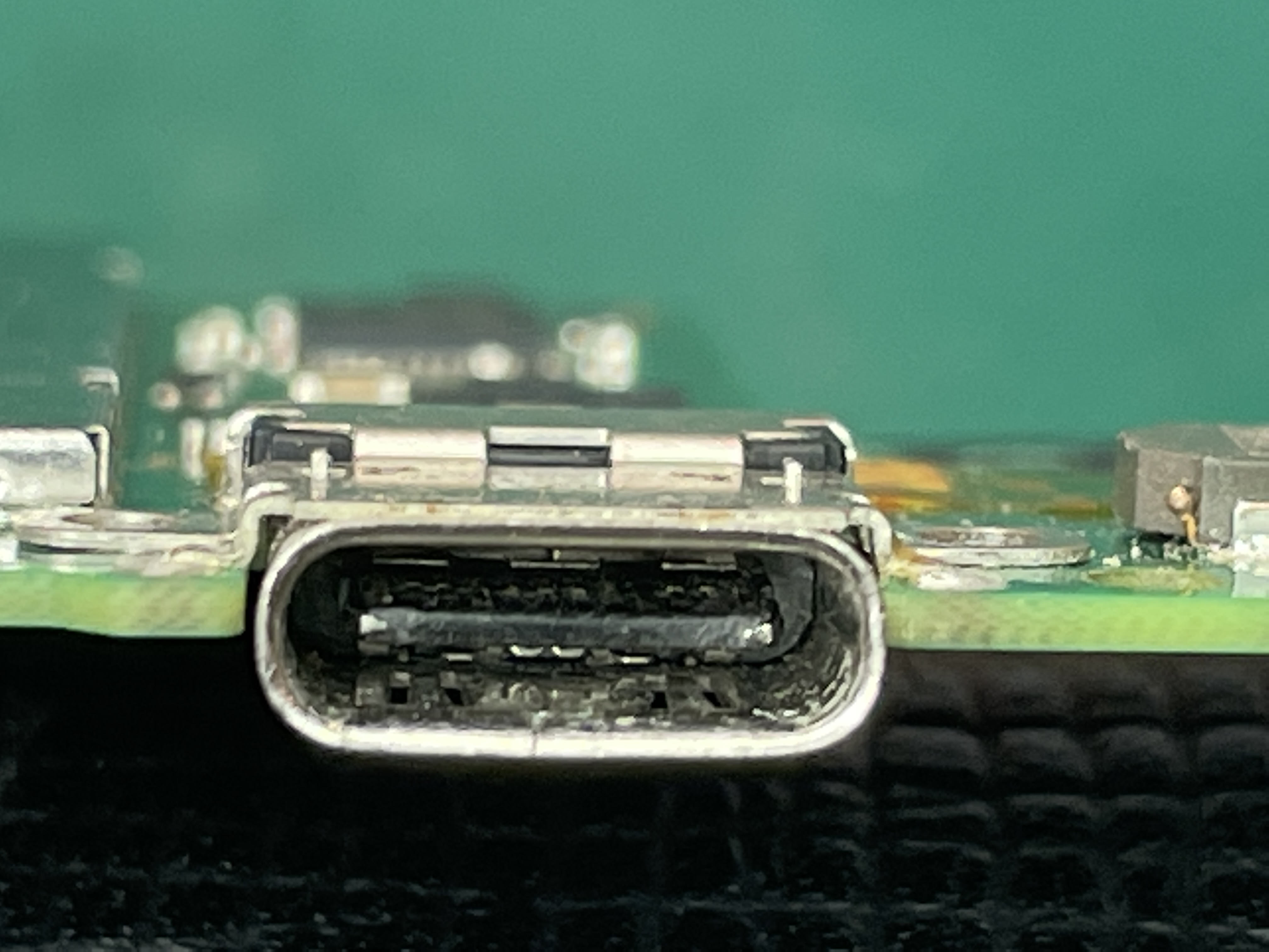
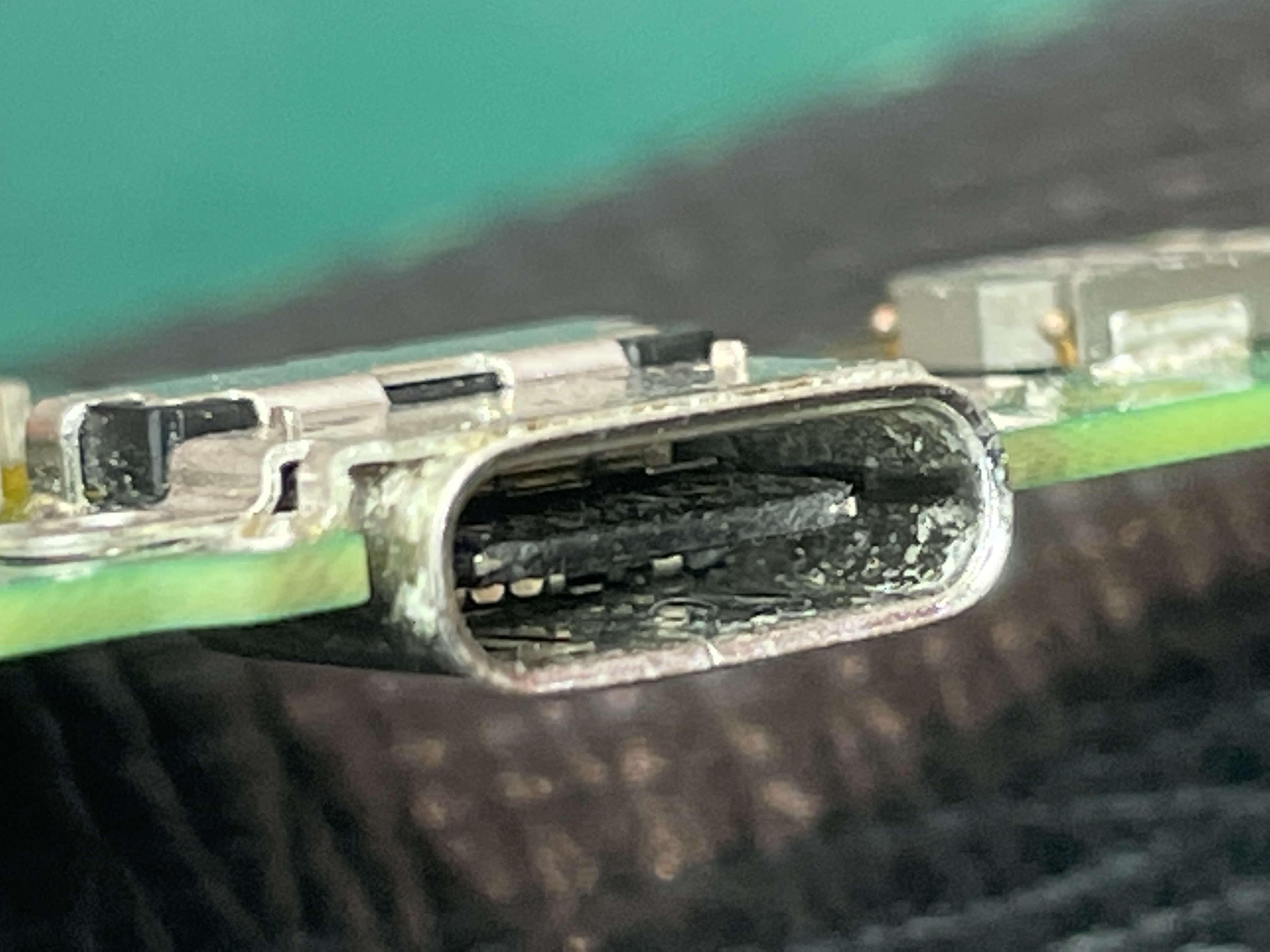
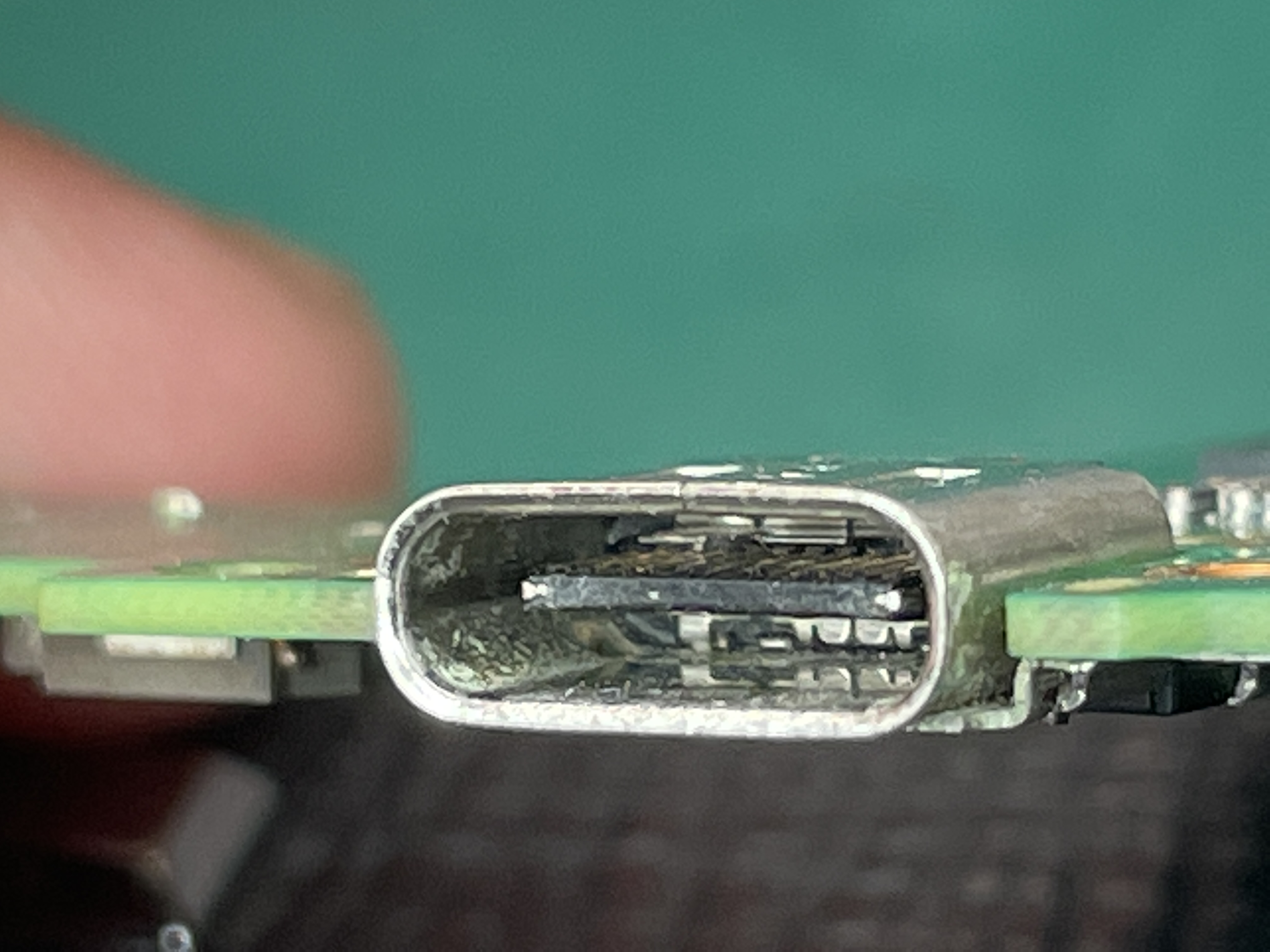
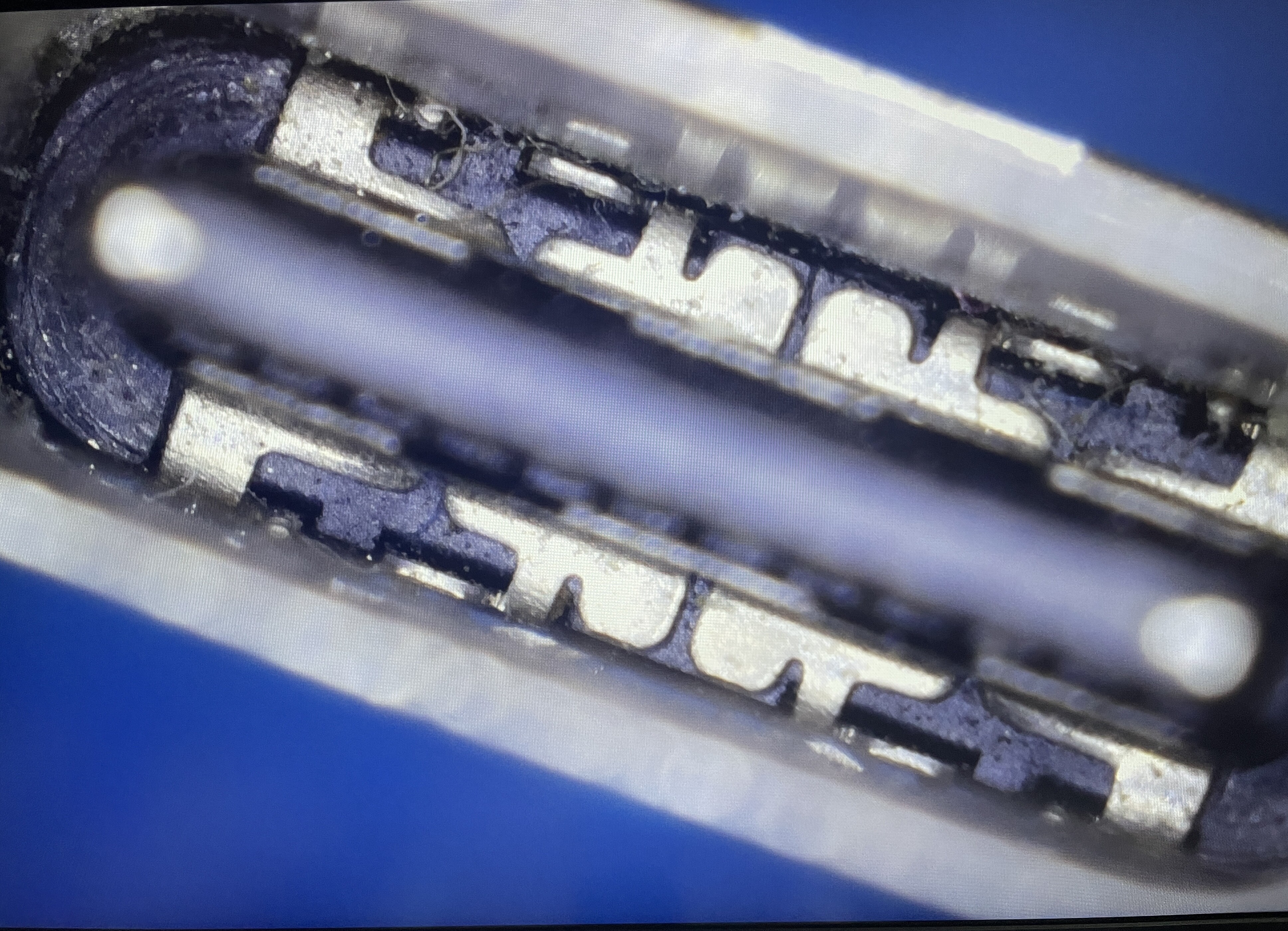
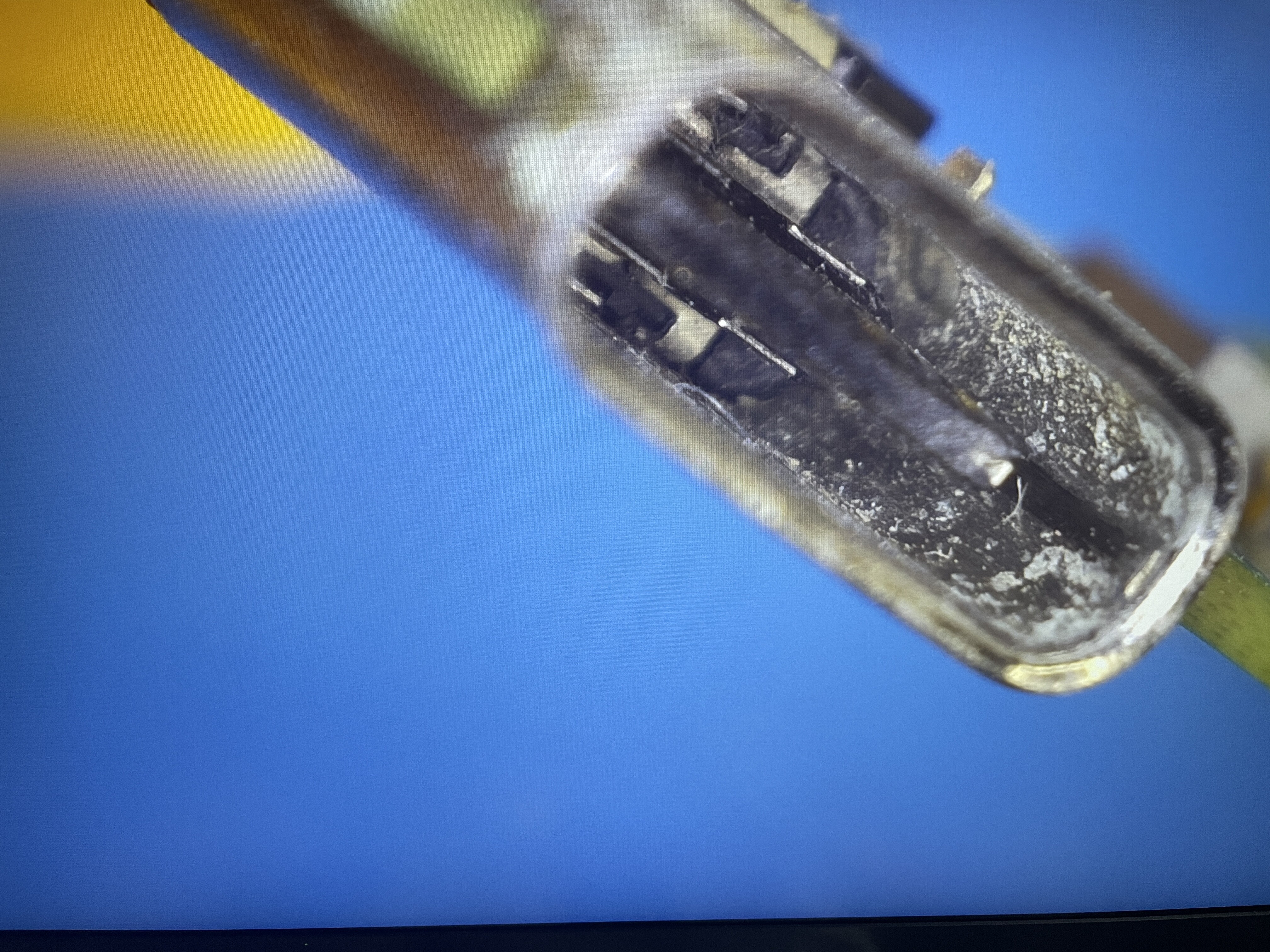
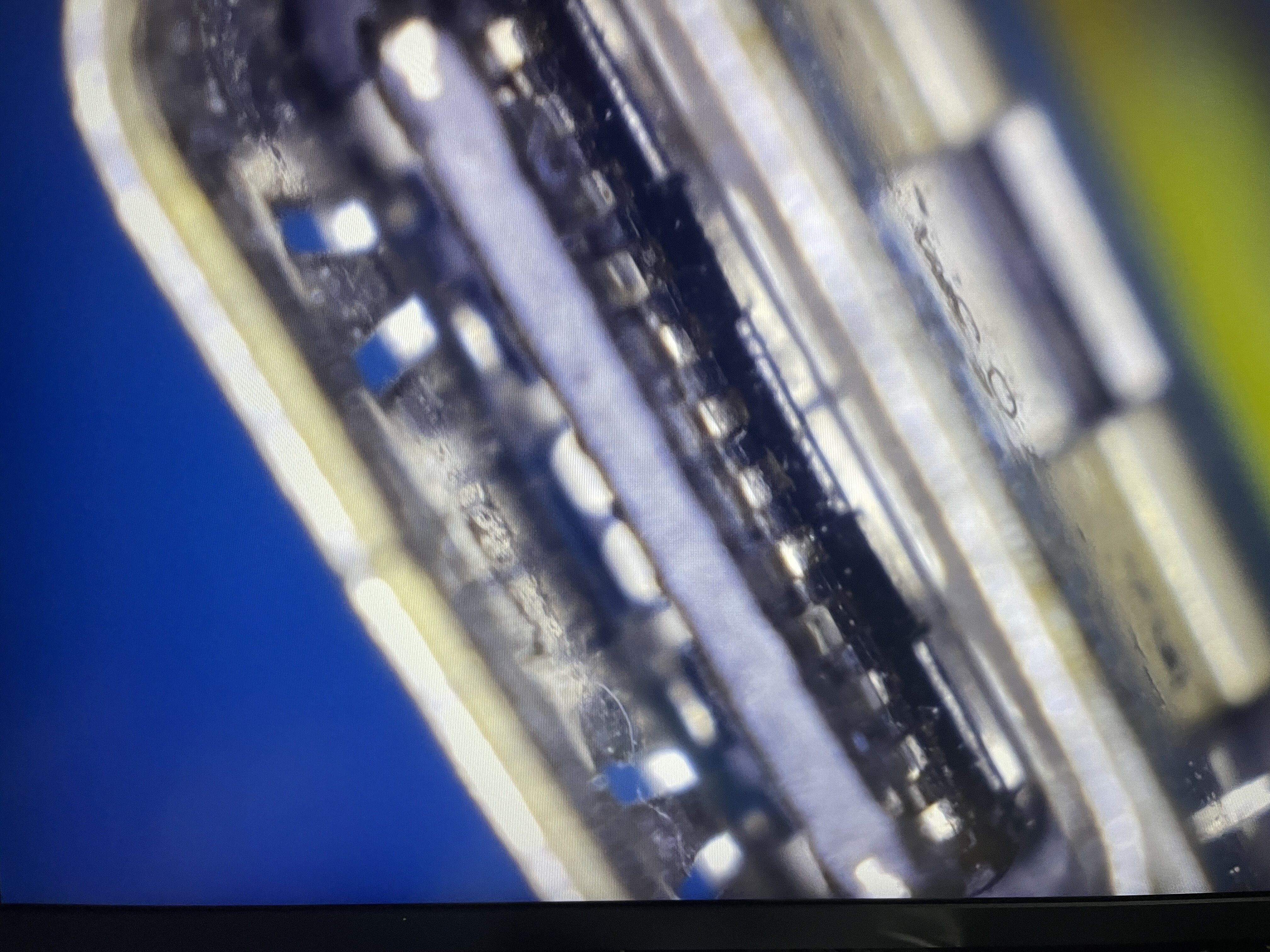
Just a couple of basic things to check first, take a look inside the USB port and while your at it also the LCD connector and check for any bent pins or damage (just in case)

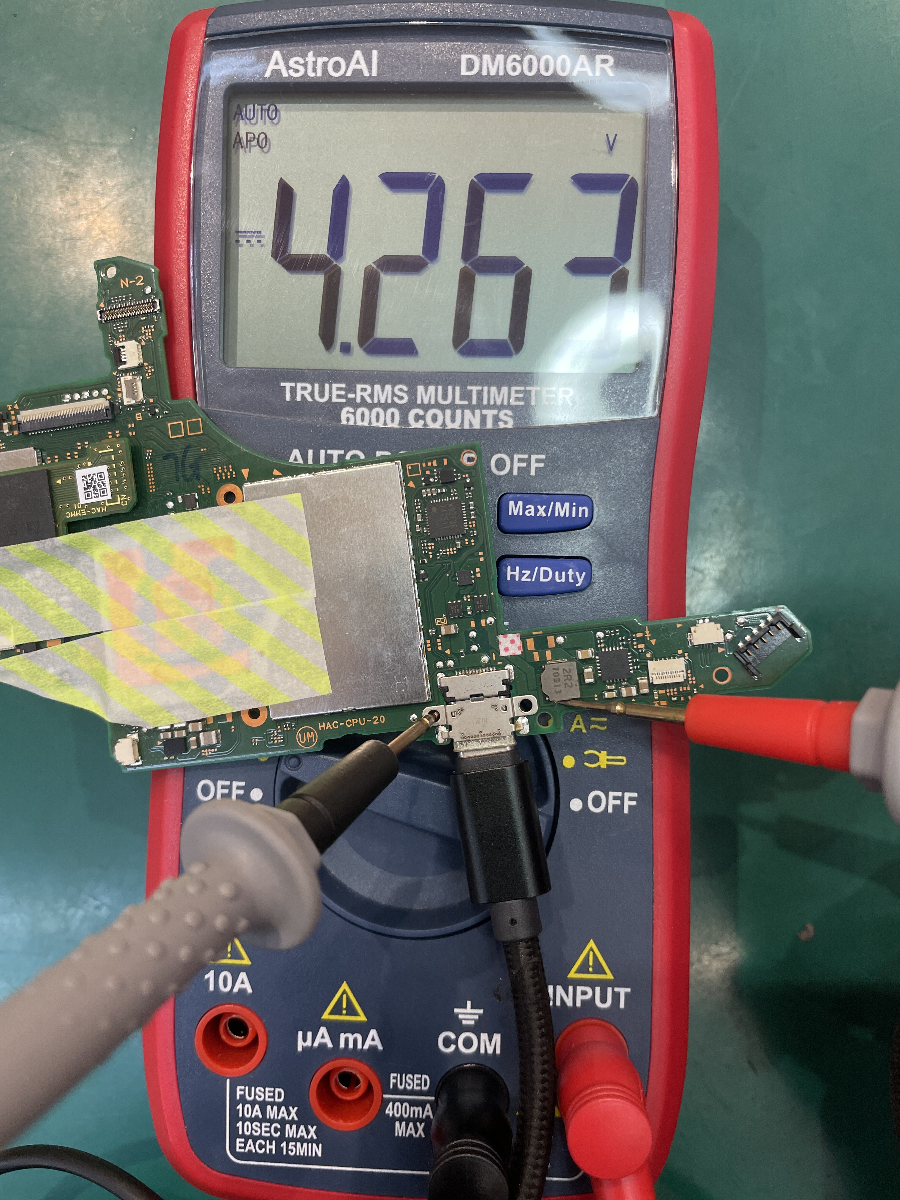
Afterwards, disconnect battery and take the measurments outlined in this post

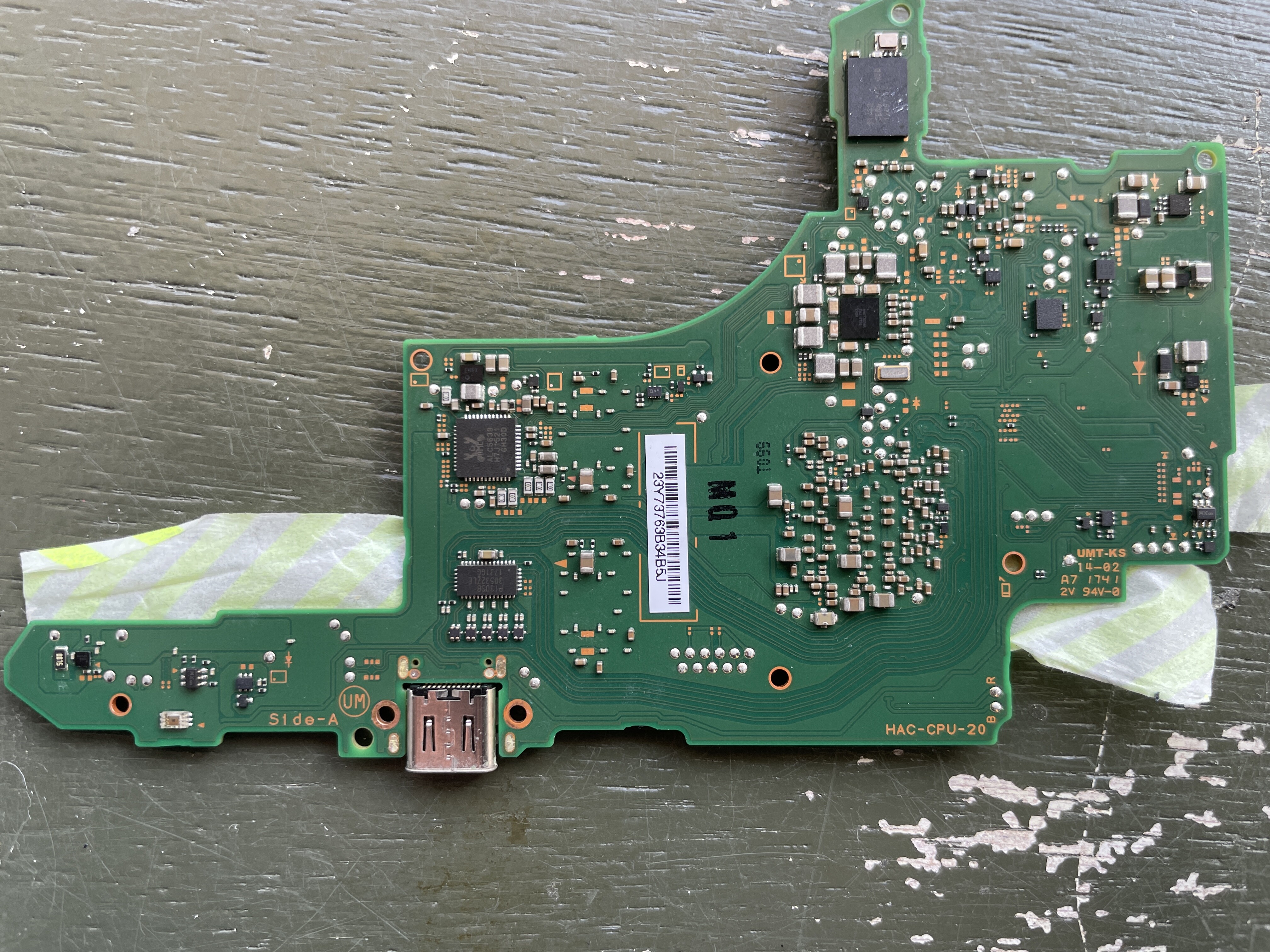
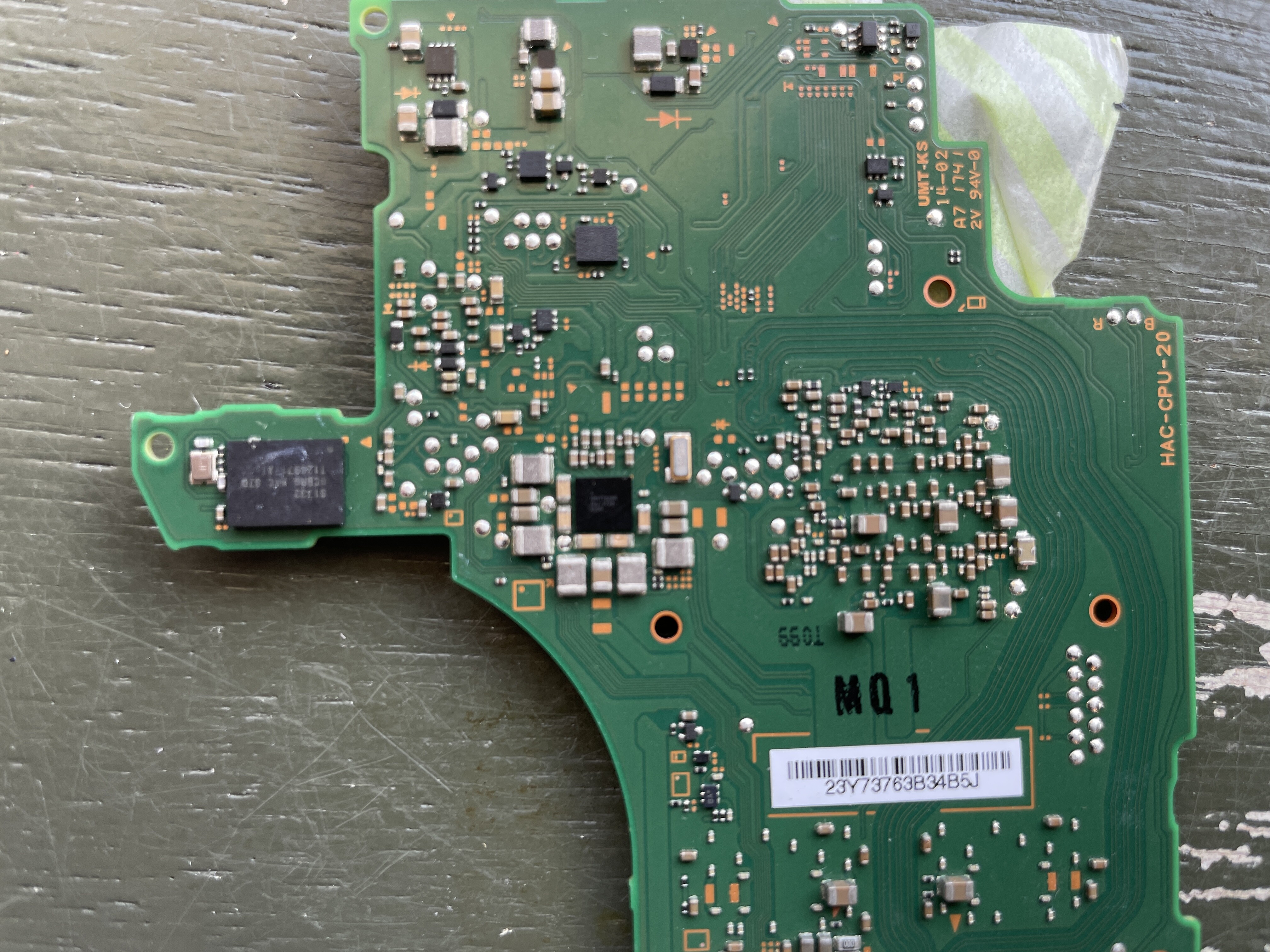
at the main Max PMIC shown in the second photo, resistance relative to ground, put your black probe on ground (screw hole pad) and red probe at the points and let me know the readings :+1:

1 Like

SMALL chance HAC-CPU-20 is exploitable model, so check with PC if it’s in AutoRCM model

2 Likes

Resistance values may not change significantly and significantly

kΩ changes a lot every second, but

I’d like to illustrate this with an image, but I get “An error occurred: sorry, you can’t embed media items in a post.” and can’t upload it, do you know why?

Hi, I would like to check AutoRCM, can I find it by connecting to my PC, I have Windows. What software do you use to check it?

TegraRcmGUI_v2.6
check here

1 Like

It’s just because your a new user, just upload to image host and format like this

imgur (dot) com/yourimage

(for example)

You may need to disconnect the EMMC module if you don’t have the RCM Jig

1 Like

It changes every second or every time I take a measurement. Why is this?

Black
Upper 4.6kΩ
Bottom 4.6kΩ

Light blue
Upper 4.6kΩ
Lower 0.4Ω

Orange
Upper 4.1MΩ
Lower 0.2Ω

Pink(Varies widely)
Upper 0.7MΩ
27kΩ

Blue
Right 29.6Ω
Left 30Ω

Yellow
Left 30Ω
Right 0.2Ω

White
Both ends 33Ω

Red
Upper 0.9kΩ
Lower 0.9kΩ

Purple
Upper 0.2Ω
Lower 0.89kΩ

In places it shows a different resistance than in the picture, is this a problem?

“An error occurred: sorry, you can’t include links in your posts.” and cannot attach URL :cry:
The colors are based on the colors in the image above

Don’t worry, it’s just because your measuring in circuit, that and some meters are twitchier (more eratic) than others.

This is all fine.

This is perhaps slightly high… though I have measured this sometimes on some board revisions and it’s normal too. We’ll keep this in mind for later as it may imply a Ram related issue, I’ll wait to see if your Switch is unpatched.

USBポートとLCDコネクターを損傷や曲がったピンの兆候がないか、点検しましたか?
(above is just asking about USB and LCD connector for anyone else reading)

新規ユーザーの方に限り、写真やリンクの添付ができない仕組みとなっております。リンクの整形方法は以下の通りです。小数点(ピリオド)の間にスペースを入れるか、括弧(カッコ)で囲むことができます。例えば、あなたのリンク(ドット)コムのようにしてください。 / yourlink (dot) com

Hopefully the above made sense :slight_smile:

1 Like

I was updating my profile and my account score went up and I was able to reply! It was a limit on the number of times per day so far!

I’m getting 4.6V to the main inductor, so I’m assuming no charging port errors!

How much is normal for the red capacitor and resistor in the image above?


Thanks, you helped me learn one thing :blush:.

Not really, this point is PSYS rail, doesn’t really confirm or deny USB issues.

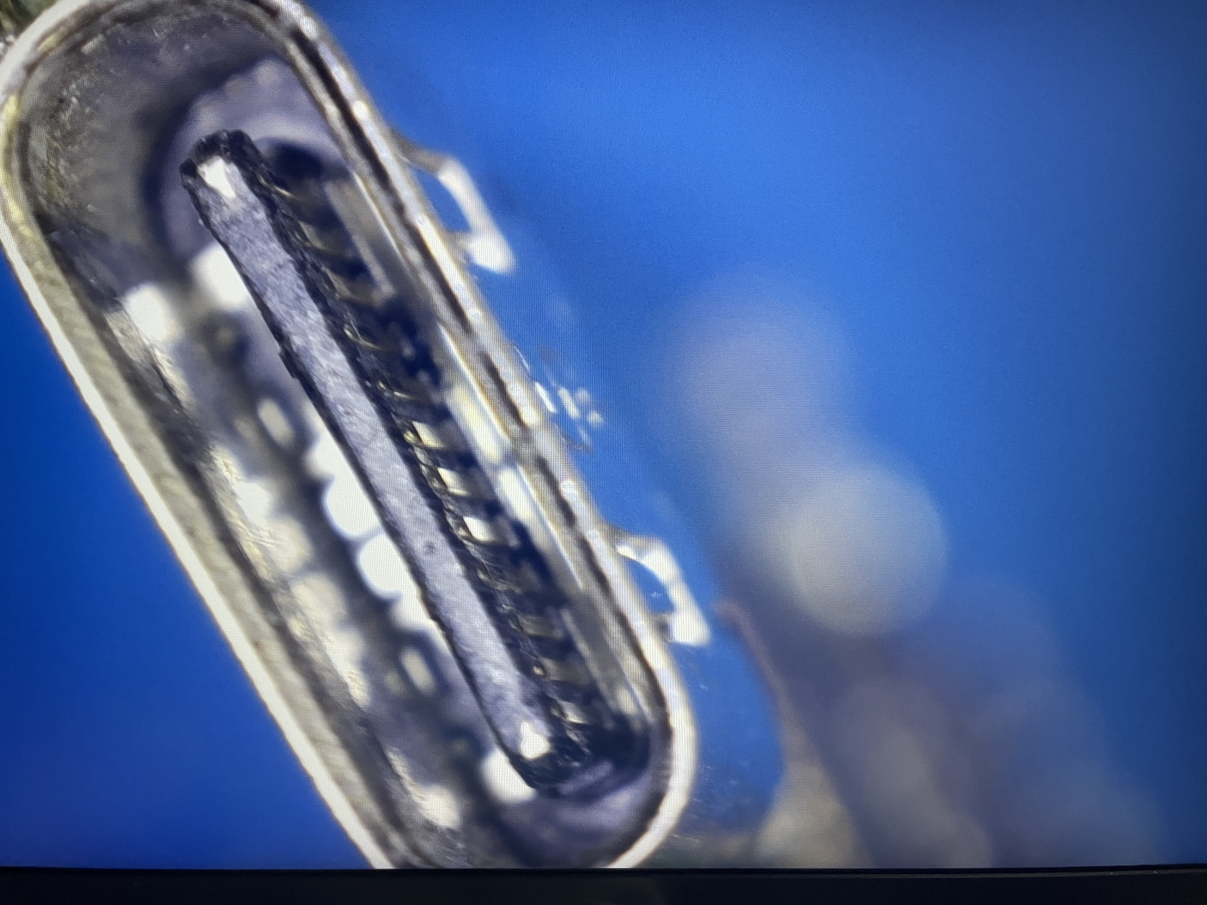
For the USB port, check it at more of an angle and look at the gold contacts / pins and check for issues. You can even give the platic stem a wiggle with some tweezers to se if there is a break too (battery disconnected of course)

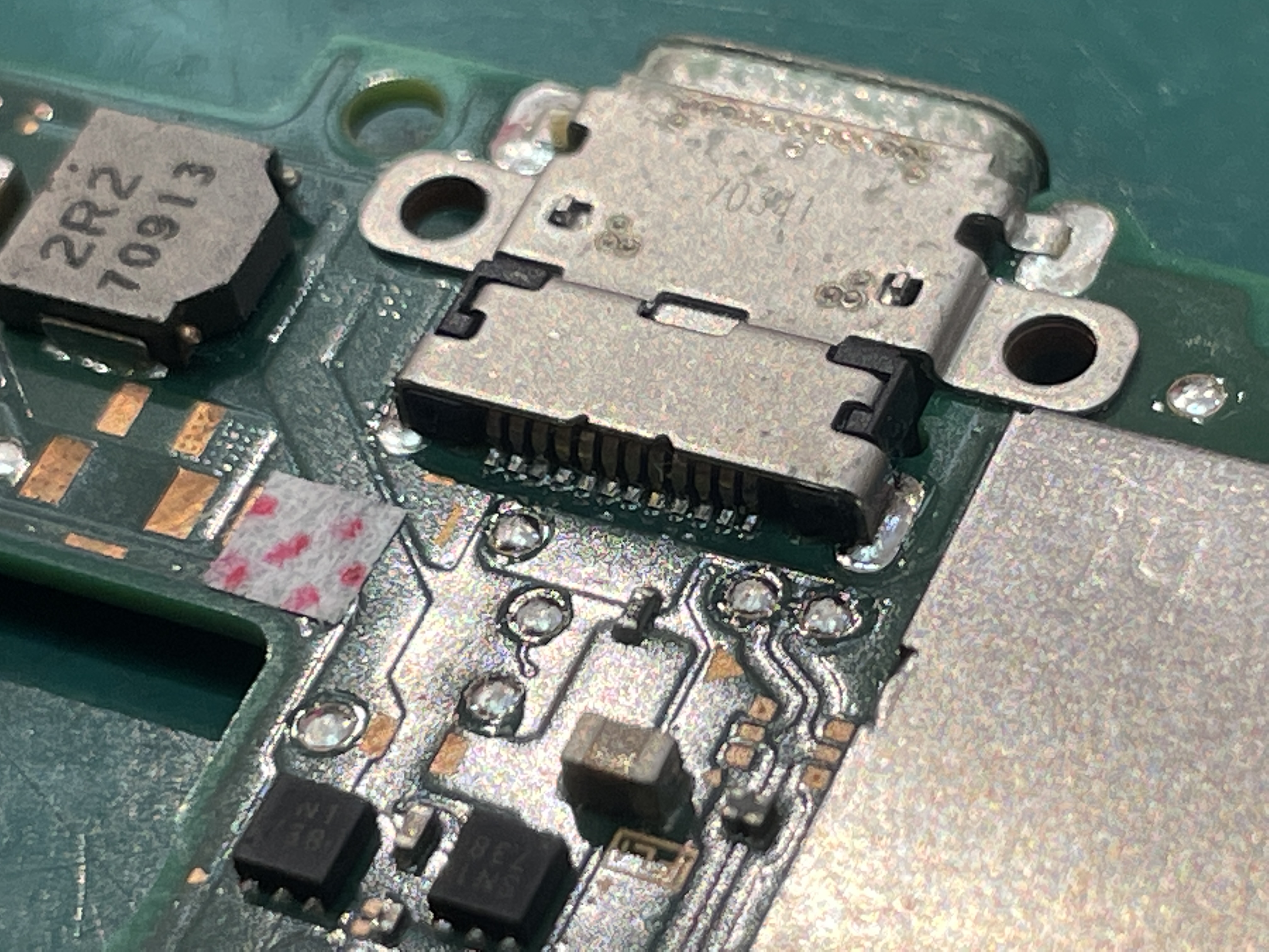
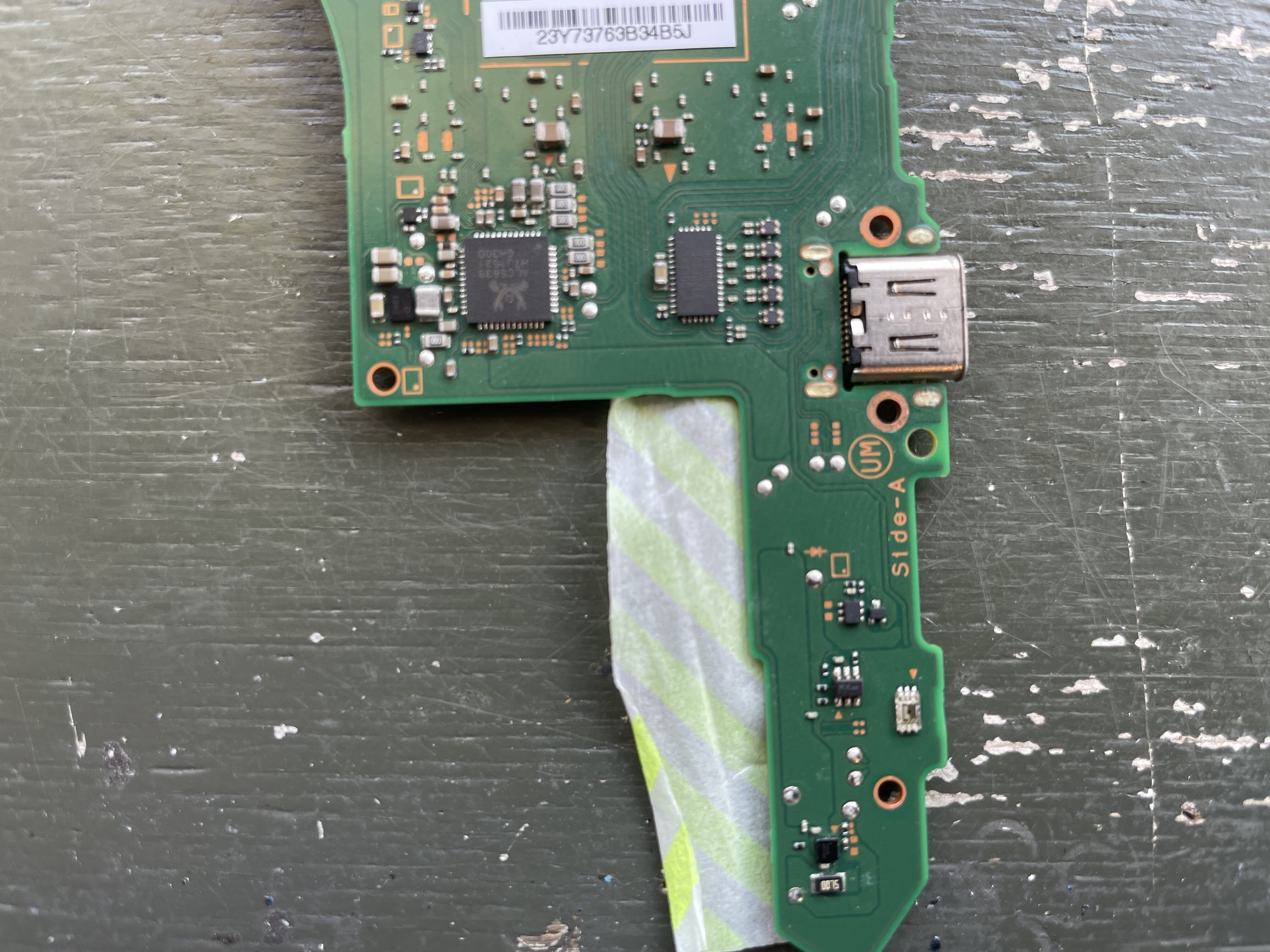
Can you take a photo of the other side of the board too

1 Like

Right now I am at a friend’s house and in a little while I will have a microscope and some test batteries at home. I also have new charging dock parts.

Right now I only have pictures from my iPhone camera, sorry.


Seems to me there is no error :thinking:


Yeah looks a little worn but generally ok.

Can you take a photo of the otherside of the board in it’s entirety so I can take a look. I primarily want to see the fuel gauge.

1 Like

Are you okay with something like this?
If there’s anywhere you want to see more magnification, I’ll take a picture.