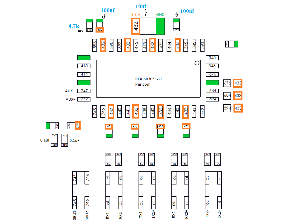
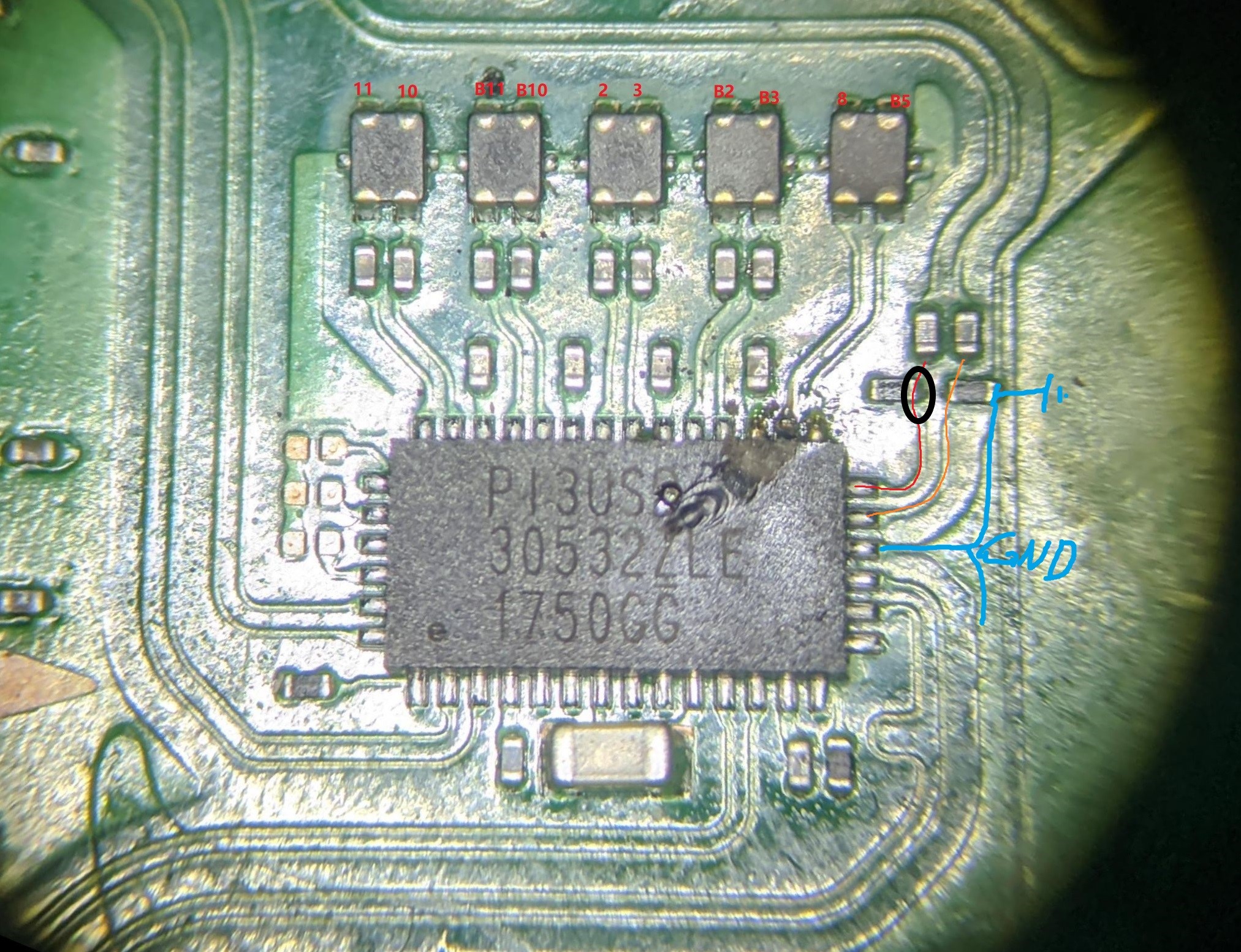
Hey guys, I have recently tried to replace p13usb since it’s the only short on the board (i was getting 0.2 Amp charging then dead). I have accidentally ripped off the pads ( Circled in Red), Is there anywhere I can connect back the trace with a jumper wire? I have also knocked out one of the resistors on the way( Circled in Blue) ( i think its the 100k ohm 0201 ) Thanks
For the bottom red circle, can I connect that to the left side of the missing resistor
P.s. can some one link me the mouser part for the resistor. I have found 3 version with different % , does it matter ? Thanks
i.imgur.co.m/YSv3rBx.jpg
i.imgur.co.m/UNPW1j8.jpg
Remove the dot between co a m. I’m not sure why post cannot include link or media ?
not sure, I normally dont measure amp when short exist. But I do find often case 10uf bottom cap area short due to pi3 chip bad. Or like my pic shown, blown trace/chip from top right choke filter
Thanks again, that was my though process when my 10uF was shorted. I try to replace the p13usb chip. if my trace is fully destroyed. Could i connect the jumper wire to the correct side the resistor (the red line in your picture)
Yes for sure, I had same dump situation before when not heating up enough and force removing the ic, ending up red and orange trace ripped.
For the jumper, best seat jumper wire under the chipset like original pad. worst situation is solder jumper onto the edge of the ic contact pin, do-able but less contact are compared to seat under
Just want to confirm connecting to the top of the resistor is the same as if the trace was under ?For the jumper do you recommend 30 awg or 32 awg enamel copper wire ( magnet wire) ? If I seat the jumper under the IC, would that cause a small bump on the IC ?
I just check the diode. My resistor are not showing any diode. Did I destoryed my resistor? When I check in ohm it show 4.7k ohm.
Happy new year. It is normal no diode value if pi3 not placed.
I would suggest connect to the side of res,since you can also link the cap above together to have firm jumper.
I use 0.1mm wire, with a little filing and place it into the missing-pad hole. The pi3 sits flat no bump
Resistor side by SMD standard, solder joint should not be Soldered over 50% of the edge surface. Do I suggest the jumper contact the resistor by the side not on the top if possible.
The cap on the same trace us just alternate point and if you end up joining together make no bad effect
Since I am on the right side of the resistor (circled in black), do I need to remove the other resistor first to make space to attach the jumper wire to the side of the resistor? What do you mean by solder joint should not exceed 50% of the edge surface?
I will connect the wire to the side of the resistor and the end of the capacitor. Sorry for all my noob questions
How do I ensure a tight joint. I pre tin the wire and add some flux to the location and just solder it as close as possible ? What kind of solder tip do I use between the resistor ? iLS ?
When you mean buzz, is it continuity mode from the broke pad to the resistor beside it ? To see if it is bridge ?
Me personally, I’d tin the pad with leaded first and then place wire next to it, touch iron to joint and slide and butt the jumper up to the resistors end-cap as close as possible, keep excess length on your jumper wire so you can easily manipulate it and when your done cut off the excess.
I use T12 style cartridge tips, for this job i’d likely use a D24 tip, which is a “chisel” tip. I’d avoid using small pointed tips however counter intuitive it may seem